5.30
SEL-2414 Transformer Monitor Instruction Manual Date Code 20130214
Metering and Monitoring
Monitoring
When EDFTC is set to Y (yes), the transformer constants shown in Table 5.14 are
in effect and the first seven individual settings are not accessible (BFFA and
TRLIFE are accessible). When EDFTC is set to N (no), the individual
transformer constant settings are all accessible. These default values are a starting
place only and should be replaced by transformer specific values whenever
possible. The default constants assume Cooling Stage 1 is ONAN (Oil Natural,
Air Natural), Cooling Stage 2 is ONAF (Oil Natural, Air Forced), and Cooling
Stage 3 is OFAF or ODAF (Oil Forced or Directed, Air Forced). Many
transformers have a Cooling Stage 3 consisting of ONAF, with a second stage of
fans. In this scenario, the default values should not be used.
Hot-Spot Thermal Time Constant (T[x]Ths[y]).
Range: 0.01–20.00 hours, in 0.01-hour steps
IEEE C57.91-1995, Section 7.2.6 states that the winding time constant, H (Ths),
is the time it takes the winding-temperature rise over oil-temperature rise to reach
63.2 percent of the difference between final rise and initial rise during a load
change. The winding time constant may be estimated from the resistance cooling
curve during thermal tests or calculated by the manufacturer using the mass of
the conductor materials.
The thermal element uses this constant in calculating the winding hot-spot
temperature.
Constant to Calculate FAA (T[x]BFFA).
Range: 0–100000, in steps of 1
IEEE C57.91-1995, Section 5.2 states that B (BFFA) is an empirical constant,
typically equal to 15000. Table 5.14 lists this value as the default. You can select
other values from within a range of 0 to 100000.
The thermal element uses this constant to calculate the transformer insulation
aging acceleration factor (FAA).
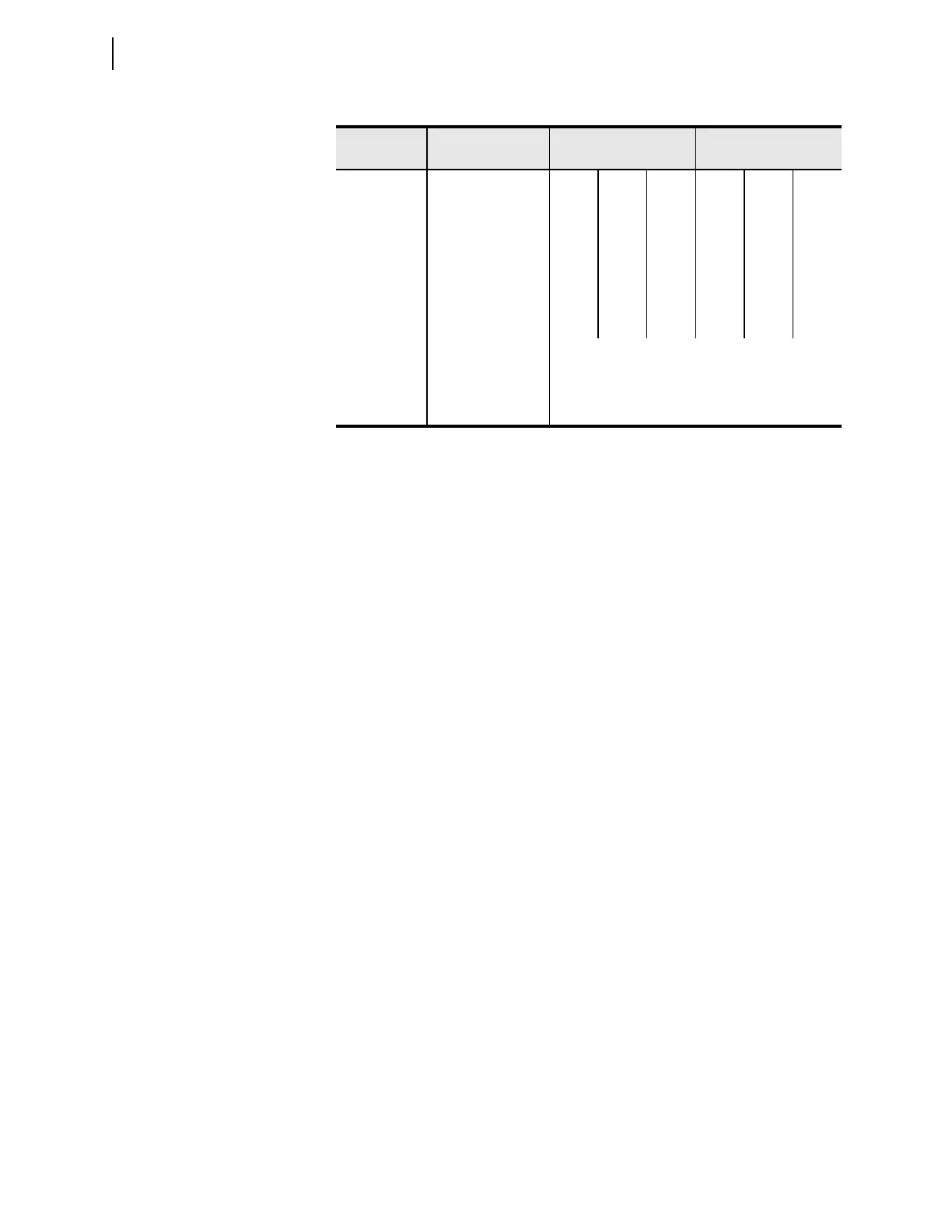
Table 5.14 Default Transformer Constants
IEEE C57.91:
1995
Cooling Stage
Settings
THwr
a
= 55°C
a
THwr = average winding rise over ambient at rated load.
THwr
a
= 65°C
CS = 1 CS = 2 CS = 3 CS = 1 CS = 2 CS = 3
ΔΘ
TO,R
T[x]THor[y] (°C) 45° 40° 37° 55° 50° 45°
ΔΘ
H,R
T[x]THgr[y] (°C) 20° 25° 28° 25° 30° 35°
R T[x]RATL[y] 3.0 3.5 5.0 3.2 4.5 6.5
τ
TO,R
T[x]OTR[y] (hours) 3.0 2.0 1.25 3.0 2.0 1.25
n T[x]EXPn[y] 0.8 0.9 1.0 0.8 0.9 1.0
m T[x]EXPm[y] 0.8 0.8 1.0 0.8 0.8 1.0
τ
H
T[x]Ths[y] (hours) 0.08
B T[x]BFFA 15000
Nominal
Insulation Life
TRLIFE 180000