Phaser 6000/6010 and WC 6015 MFP Xerox Internal Use Only 10-5
Wiring
Phaser 6000/6010 Printer Plug/Jack Designations
This chapter contains the plug/jack designators, locator diagrams, and wiring
diagrams. The Plug/Jack Locator diagrams show the P/J locations within the
printer. Use these illustrations to locate connections called out in the
troubleshooting procedures presented in Sections 3, 4, and 5.
1. Locate the P/J connector designator in the first column of the table.
2. With this information, go to the map listed in the Map column.
3. Use the coordinates to locate the connection indicated on the map by its P/J
designation number.
4. The Remarks column provides a brief description of each connection.
For WorkCentre 6015 MFP plug and jack designators, see “WorkCentre 6015 MFP
Printer Plug/Jack Designations” on page 10-19.
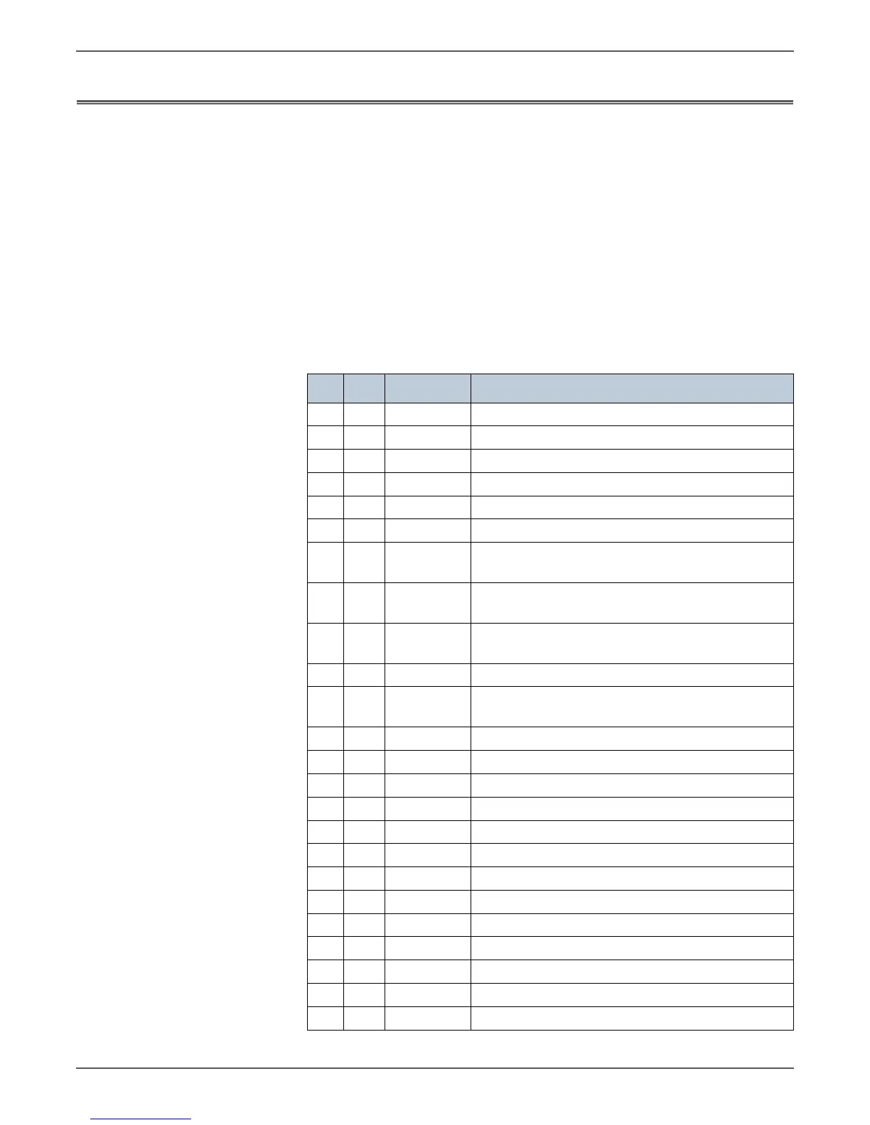
Phaser 6000/6010 Plug and Jack Designators
P/J Map Coordinates Remarks
1 2 I-122 Connects LED Driver Board and LED/MCU CABLE
1 2 I-123 Connects LED Driver Board and IP Board
2 2 J-122 Connects LED Driver Board and FFC LPH (M)
3 2 J-122 Connects LED Driver Board and FFC LPH (Y)
4 2 J-123 Connects LED Driver Board and FFC LPH (K)
5 2 J-123 Connects LED Driver Board and FFC LPH (C)
10 3 I-134 Connects MCU Board and Deve Drive Assy (K Mode
Switching Solenoid)
12 3 J-134 Connects MCU Board and RKN SNS Harness (6010N
Only)
12 3 J-134 Connects MCU Board and RKN SNS Harness (6000B
Only)
13 3 H-133 Connects MCU Board and DCKR Harness
14 3 J-134 Connects MCU Board and ADC1 Harness (6010N
Only)
14 3 J-134 Connects MCU Board and ADC Harness (6000B Only)
15 3 I-133 Not Connected
16 3 I-133 Connects MCU Board and Main MOT Harness
17 3 H-134 Connects MCU Board and LVPS
18 3 I-134 Connects MCU Board and Fuser
19 3 I-134 Connects MCU Board and Feed Solenoid
20 3 H-134 Connects MCU Board and Dispense MOT Harness
21 3 I-134 Connects MCU Board and HVPS Harness
22 3 J-134 Connects MCU Board and ESS FFC Assy
23 3 I-134 Connects MCU Board and LED/MCU Cable
25 3 I-134 Connects MCU Board and Registration Clutch
26 3 I-134 Connects MCU Board and Fuser
111 2 G-123 Not Connected
 Loading...


