10 CAN/LIN Triggering and Serial Decode
262 InfiniiVision 7000B Series Oscilloscopes User’s Guide
Setup for CAN Signals
Setup consists of connecting the oscilloscope to a CAN signal, using the
Signals Menu to specify the signal source, baud rate, and sample point.
To set up the oscilloscope to capture CAN signals, use the Signals softkey
which appears in both the Trigger Menu and the Serial Decode Menu:
1 Press [Label] to turn on labels.
2 Press [Trigger]; then, select the CAN trigger type.
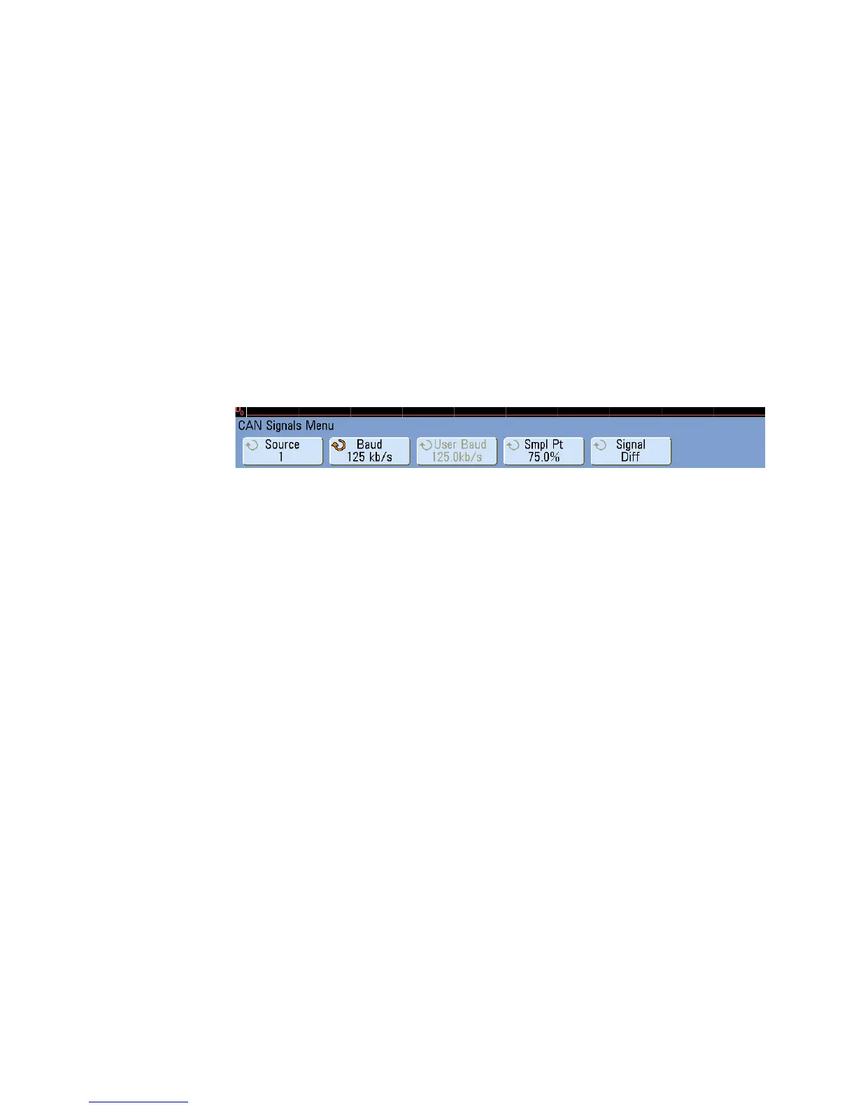
3 Press the Signals softkey to open the CAN Signals Menu.
4 Press Source; then, select the channel for the CAN signal.
The CAN label for the source channel is automatically set, and the
channel you select is shown in the upper- right corner of the display
next to “CAN”.
5 Set the trigger level.
• For analog channels, turn the Trigger Level knob.
• For digital channels, press the [Digital] key and the Thresholds softkey
to access the threshold level setting softkeys.
The value of the trigger level or digital threshold is displayed in the
upper- right corner of the display.
6 Press the Signal softkey and select the type and polarity of the CAN
signal. This also automatically sets the channel label for the source
channel.
• CAN_H — The actual CAN_H differential bus
Dominant low signals:
• CAN_L — The actual CAN_L differential bus signal
• Rx — The Receive signal from the CAN bus transceiver
• Tx — The Transmit signal from the CAN bus transceiver
 Loading...


