CAN/LIN Triggering and Serial Decode 10
InfiniiVision 7000B Series Oscilloscopes User’s Guide 277
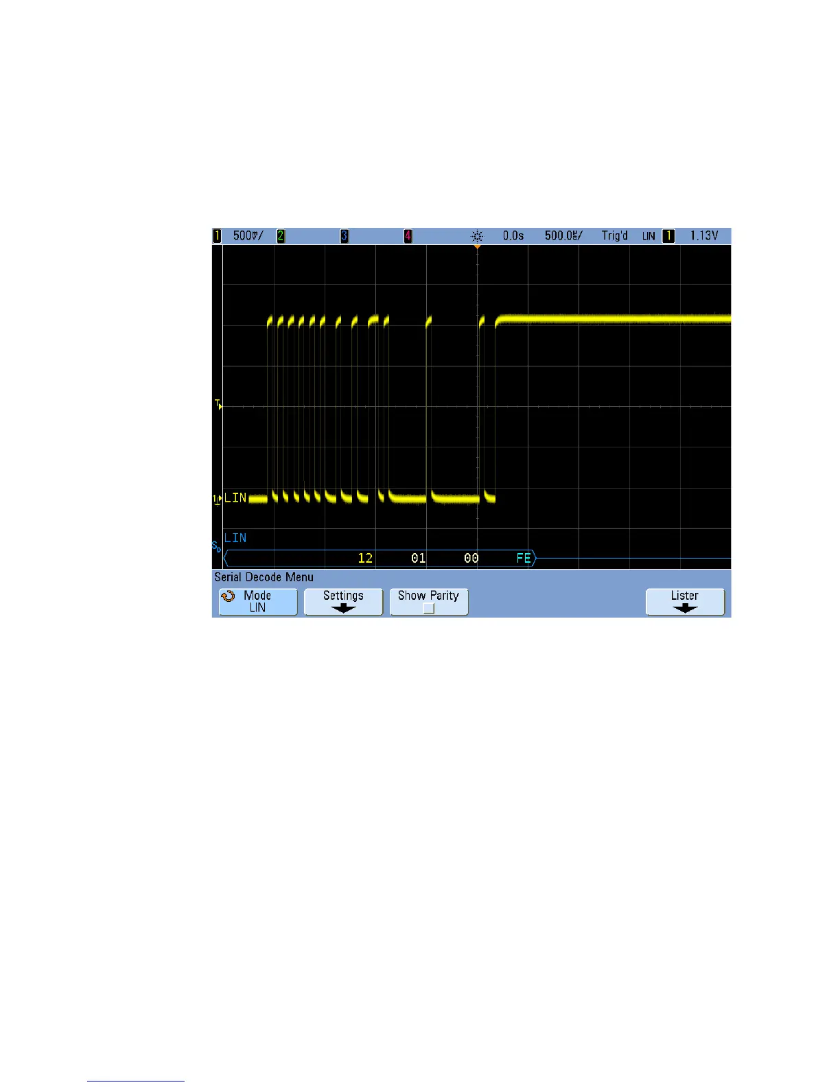
Interpreting LIN Decode
• Angled waveforms show an active bus (inside a packet/frame).
• Mid- level blue lines show an idle bus (LIN 1.3 only).
• The hexadecimal ID and parity bits (if enabled) appear in yellow. If a
parity error is detected the hexadecimal ID and parity bits (if enabled)
appear in red.
• Decoded hexadecimal data values appear in white.
• For LIN 1.3, the checksum appears in blue if correct, or red if
incorrect. The checksum always appears in white for LIN 2.0.
• Decoded text is truncated at the end of the associated frame when
there is insufficient space within frame boundaries.
• Red dots in the decode line indicate that there is data that is not being
displayed. Scroll or expand the horizontal scale to view the information.
• Unknown bus values (undefined or error conditions) are drawn in red.
• If there is an error in the synch field, SYNC will appear in red.
 Loading...


