12 I
2
S Triggering and Serial Decode
310 InfiniiVision 7000B Series Oscilloscopes User’s Guide
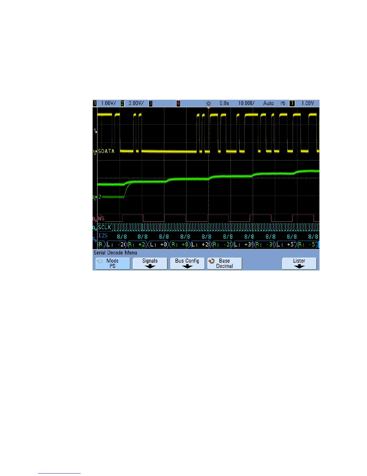
Interpreting I
2
S Decode
• Angled waveforms show an active bus (inside a packet/frame).
• Mid- level blue lines show an idle bus.
• In the decoded data:
• Right channel data values appear in green along with the “R:”
characters.
• Left channel data values appear in white along with the “L:”
characters.
• Decoded text is truncated at the end of the associated frame when
there is insufficient space within frame boundaries.
• Red dots in the decode line indicate that more data can be displayed.
Scroll or expand the horizontal scale to view the data.
• Aliased bus values (undersampled or indeterminate) are drawn in red.
• Unknown bus values (undefined or error conditions) are drawn in red.

 Loading...


