11 I
2
C/SPI Triggering and Serial Decode
292 InfiniiVision 7000B Series Oscilloscopes User’s Guide
Setup for SPI Signals
Serial Peripheral Interface (SPI) trigger setup consists of connecting the
oscilloscope to a clock, data, and framing signal.
To set up the oscilloscope to capture SPI signals, use the Signals softkey
which appears in both the Trigger Menu and the Serial Decode Menu:
1 Press [Label] to turn on labels.
2 Press [Trigger]; then, select the SPI trigger type.
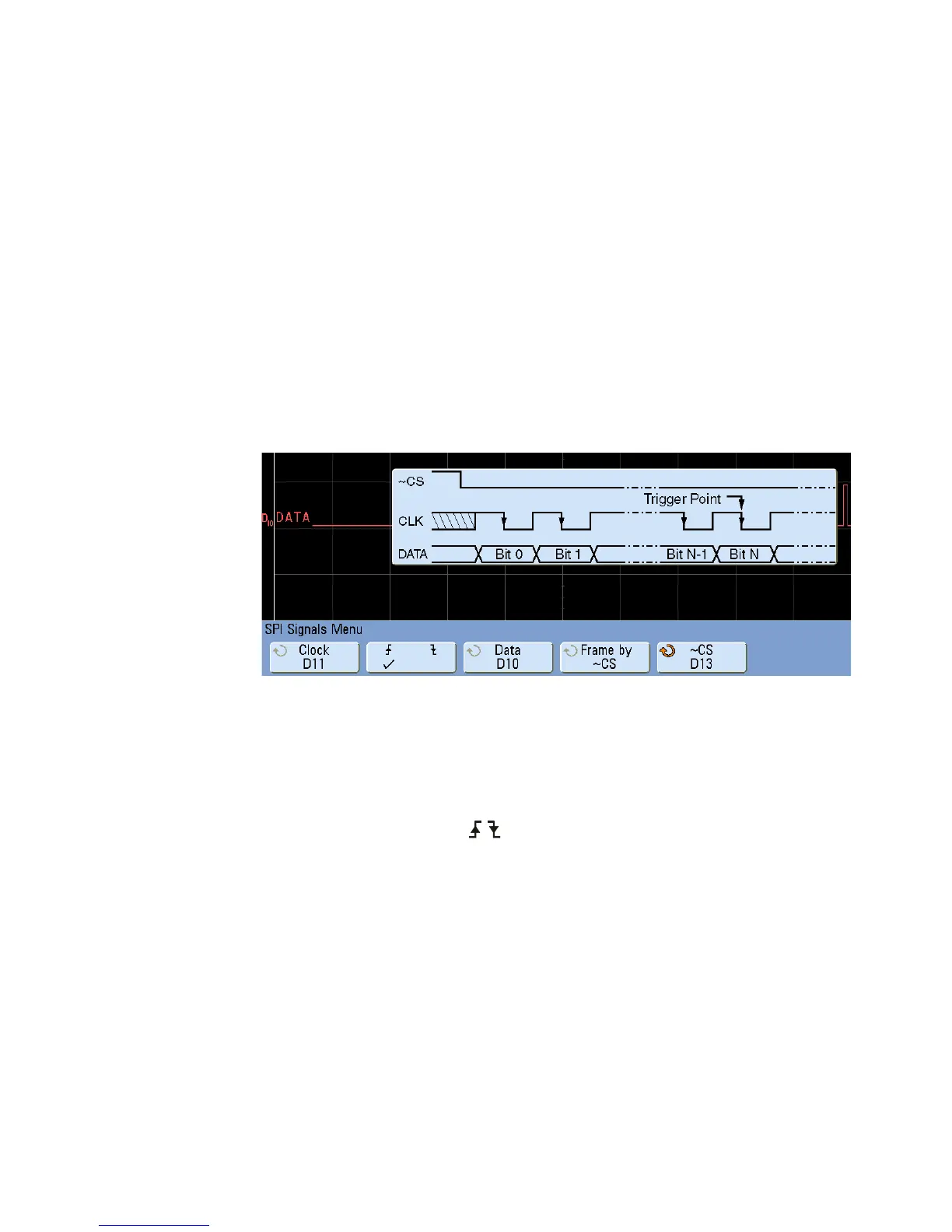
3 Press the Signals softkey. The SPI Signals Menu will be displayed.
4 Press the Clock softkey or turn the Entry knob to select the channel
connected to the SPI serial clock line.
As you press the Clock softkey (or rotate the Entry knob), the CLK label
for the source channel is automatically set and the channel you select is
shown in the upper- right corner of the display next to “SPI”.
5 Press the slope softkey ( ) to select rising edge or falling edge for
the selected Clock source.
This determines which clock edge the oscilloscope will use to latch the
serial data. When you press the slope softkey, the graphic shown on the
display changes to show the current state of the clock signal.
6 Press the Data softkey or turn the Entry knob to select the channel that
is connected to the SPI serial data line. (If the channel you selected is
off, switch it on.)
As you press the Data softkey (or rotate the Entry knob), the DATA label
for the source channel is automatically set and the channel you select is
shown in the upper- right corner of the display next to “SPI”.

 Loading...


