11 I
2
C/SPI Triggering and Serial Decode
282 InfiniiVision 7000B Series Oscilloscopes User’s Guide
Setup for I
2
C Signals
An I
2
C (Inter- IC bus) trigger setup consists of connecting the oscilloscope
to the serial data (SDA) line and the serial clock (SCL) line.
To set up the oscilloscope to capture I
2
C signals, use the Signals softkey
which appears in the Trigger Menu or the Settings softkey which appears
in the Serial Decode Menu:
1 Press [Label] to turn on labels.
2 Press [Trigger]; then, select the I
2
C trigger type.
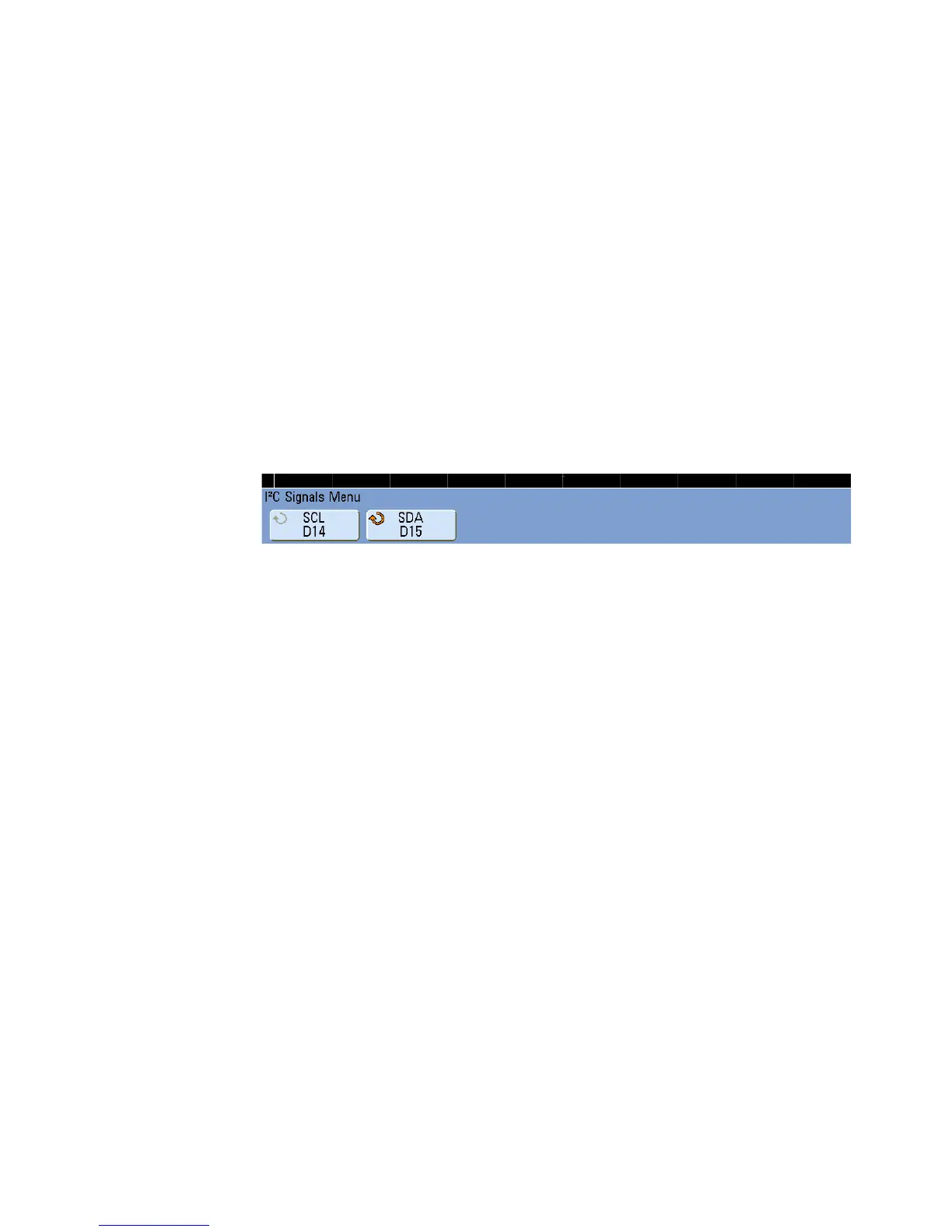
3 Press the Signals softkey to display the I
2
C Signals Menu.
4 Connect an oscilloscope channel to the SCL (serial clock) line in the
device under test, then set the SCL clock channel softkey to that
channel.
As you press the SCL softkey (or rotate the Entry knob), the SCL label
for the source channel is automatically set and the channel you select is
shown in the upper- right corner of the display next to “I
2
C”.
5 Connect an oscilloscope channel to the SDA (serial data) line in the
device under test, then set the SDA data channel softkey to that
channel.
As you press the SDA softkey (or rotate the Entry knob), the SDA label
for the source channel is automatically set and the channel you select is
shown in the upper- right corner of the display next to “I
2
C”.
6 Set the trigger levels for the SCL and SDA signals to the middle of the
signals:
• If your I
2
C signals are connected to analog channels, press the SCL
softkey and rotate the Trigger Level knob, then press the SDA softkey
and rotate the Trigger Level knob.
• If your I
2
C signals are connected to digital channels (this applies to
MSO model oscilloscopes only), press the [Digital] key and the
Thresholds softkey to access the threshold level setting softkeys and
set the thresholds to the approximate middle of the signals.
 Loading...


