17 Digital Channels
376 InfiniiVision 7000B Series Oscilloscopes User’s Guide
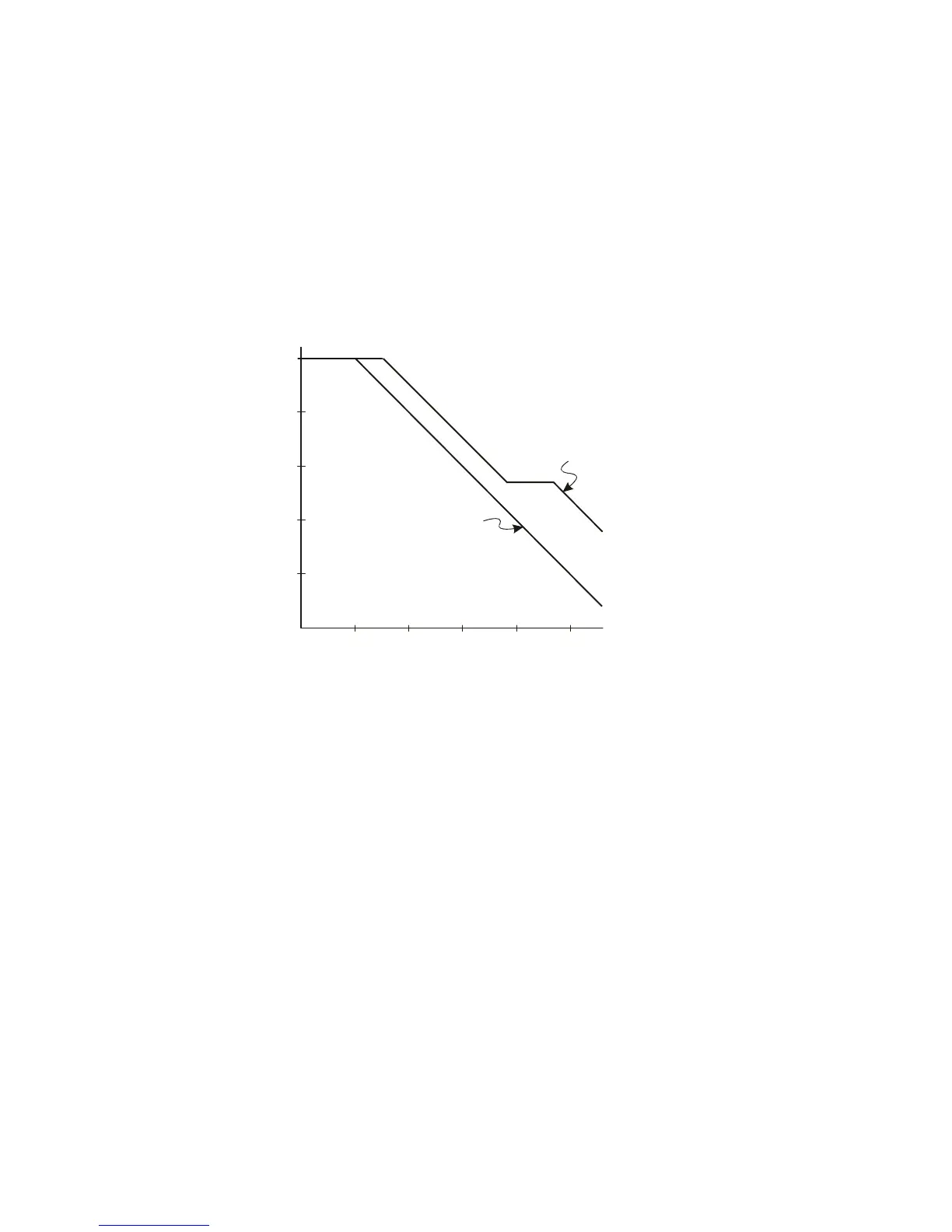
The impedance plots for the two models are shown in these figures. By
comparing the two plots, you can see that both the series tip resistor and
the cable’s characteristic impedance extend the input impedance
significantly. The stray tip capacitance, which is generally small (1 pF),
sets the final break point on the impedance chart.
Figure 38 Impedance versus Frequency for Both Probe Circuit Models
The logic probes are represented by the high- frequency circuit model
shown above. They are designed to provide as much series tip resistance
as possible. Stray tip capacitance to ground is minimized by the proper
mechanical design of the probe tip assembly. This provides the maximum
input impedance at high frequencies.
Probe Grounding
A probe ground is the low-impedance path for current to return to the
source from the probe. Increased length in this path will, at high
frequencies, create large common mode voltages at the probe input. The
voltage generated behaves as if this path were an inductor according to
the equation:
100 k
10 k
1 k
100
10
1
10 k Hz 100 k Hz 1 MHz 10 M Hz 100 M Hz 1 GHz
High
Frequency
Model
Typical
Model
Frequency
Impedance

 Loading...


