11 I
2
C/SPI Triggering and Serial Decode
298 InfiniiVision 7000B Series Oscilloscopes User’s Guide
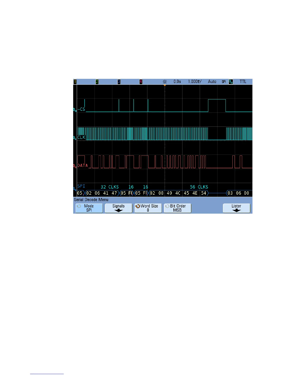
Interpreting SPI Decode
• Angled waveforms show an active bus (inside a packet/frame).
• Mid- level blue lines show an idle bus.
• The number of clocks in a frame appears in light- blue above the frame,
to the right.
• Decoded hexadecimal data values appear in white.
• Decoded text is truncated at the end of the associated frame when
there is insufficient space within frame boundaries.
• Red dots in the decode line indicate that there is data that is not being
displayed. Scroll or expand the horizontal scale to view the information.
• Aliased bus values (undersampled or indeterminate) are drawn in red.
• Unknown bus values (undefined or error conditions) are drawn in red.
 Loading...


