I
2
S Triggering and Serial Decode 12
InfiniiVision 7000B Series Oscilloscopes User’s Guide 303
6 Connect an oscilloscope channel to the SDATA (serial data) line in the
device under test, switch the channel on, then set the SDATA channel
softkey to that channel.
7 Set the trigger levels for the SCLK, WS, and SDATA signals to the
middle of the signals:
• If your I
2
S signals are connected to analog channels, press the SCLK
softkey and rotate the Trigger Level knob (not the Entry knob). Repeat
for the WS and SDATA softkeys.
• If your I
2
S signals are connected to digital channels (on MSO model
oscilloscopes only), press the [Digital] key and the Thresholds softkey
to access the threshold level setting softkeys and set the thresholds
to the approximate middle of the signals. For details see “To change
the logic threshold for digital channels” on page 368.
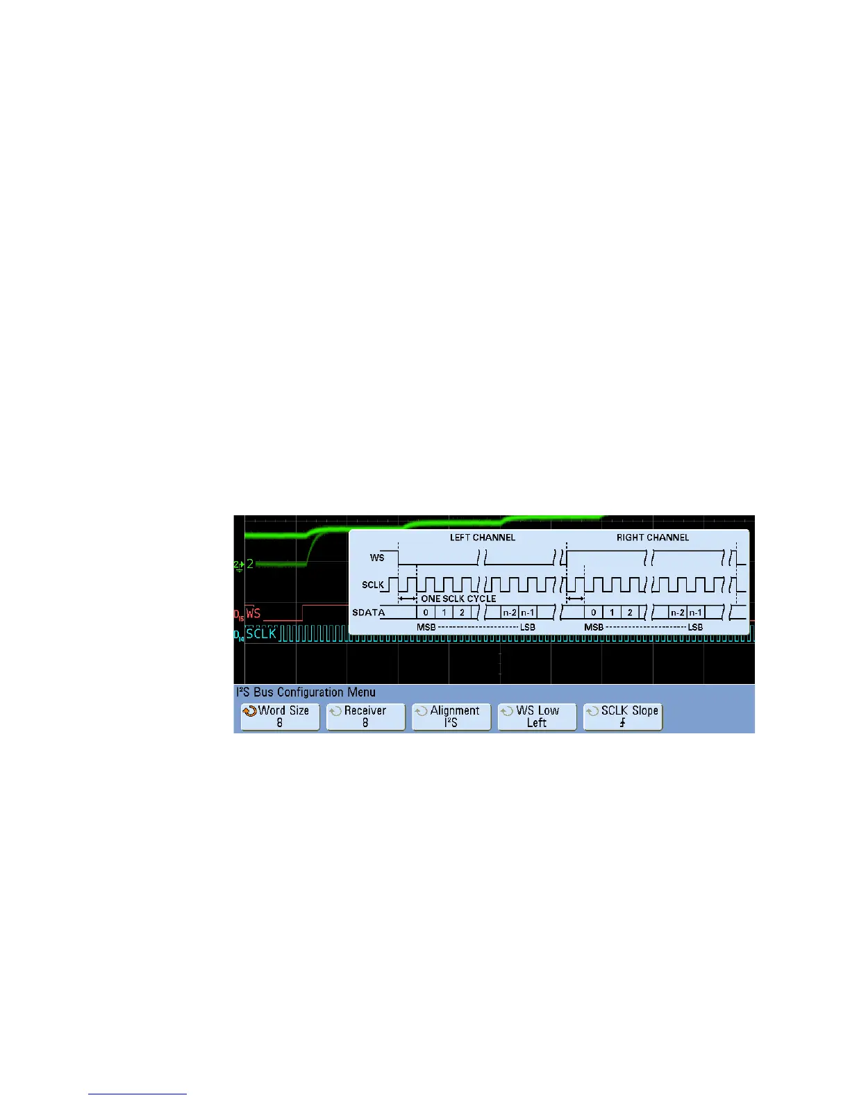
8 Press [Trigger] > Bus Config. The I
2
S Bus Configuration Menu is displayed,
along with a diagram showing WS, SCLK, and SDATA signals for the
currently specified bus configuration.
9 Press the Word Size softkey. Rotate the Entry knob to match the
transmitter word size of the device under test (from 4 to 32 bits).
10 Press the Receiver softkey. Rotate the Entry knob to match the receiver
word size of the device under test (from 4 to 32 bits).
11 Press the Alignment softkey and rotate the Entry knob to select the
desired alignment of the data signal (SDATA). The on- screen diagram
changes with your selection.
 Loading...


