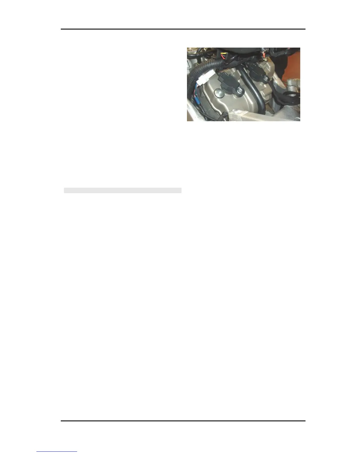
strap on engine cable harness); coil 4
with short cable: on the right of the front
side of the filter box.
Electrical characteristics:
0.7 - 0.9 Ω at ambient temperature
Pin out:
1. Power supply + Vbatt
2. Secondary circuit to ground
3. Activation from control unit
DIAGNOSIS INSTRUMENT: PARAMETERS
Example value with key ON: Current ignition ad-
vance
Example value with engine on: Indicates the cyl-
inder advance where combustion will take place.
CAUTION
BEFORE CARRYING OUT ANY TROUBLESHOOTING,
CAREFULLY READ THE GENERAL TROUBLESHOOTING
CONCEPTS FOR ELECTRICAL DEVICES AT THE BEGIN-
NING OF THE CHECK AND CONTROL SECTION IN THE
ELECTRICAL SYSTEM CHAPTER.
DIAGNOSIS INSTRUMENT: ACTIVATION
Coil 1:
The injection relay (No. 33 in the wiring diagram, placed under the right side of the saddle; CHECK,
however, the identification of the relay with the colour of the cables) is energised for 5 seconds and the
brown/yellow cable of the coil is closed to ground for 2 ms per second. Disconnect the 4-way connector
of the fuel pump to be able to hear the relay and injector activation. The continuity of the wiring is
necessary for correct activation: no error indications are displayed in case of lack of activation.
Coil 2:
The injection relay (No. 33 in the wiring diagram, placed under the right side of the saddle; CHECK,
however, the identification of the relay with the colour of the cables) is energised for 5 seconds and the
brown/red cable of the coil is closed to ground for 2 ms per second. Disconnect the 4-way connector
of the fuel pump to be able to hear the relay and injector activation. The continuity of the wiring is
necessary for correct activation: no error indications are displayed in case of lack of activation.
Coil 3:
The injection relay (No. 33 in the wiring diagram, placed under the right side of the saddle; CHECK,
however, the identification of the relay with the colour of the cables) is energised for 5 seconds and the
brown/green cable of the coil is closed to ground for 2 ms per second. Disconnect the 4-way connector
of the fuel pump to be able to hear the relay and injector activation. The continuity of the wiring is
necessary for correct activation: no error indications are displayed in case of lack of activation.
Coil 4:
RSV4 R Electrical system
ELE SYS - 185

 Loading...