•
Indication on Axone always Pulled: disconnect the terminals from the sensor and check if
there is continuity between the two PINS, with clutch released: if there is continuity, replace
sensor; if the circuit is open, it means that there is short circuit to ground of black cable from
sensor PIN 1 to engine-vehicle cable harness connector PIN C3 or of the white/purple cable
from PIN C3 to VEHICLE connector PIN 56: restore the cable harness.
Side stand sensor
Function
it tells the side stand position to the control unit
Operation / operating principle
If the gear is engaged and the side stand is unfol-
ded, and therefore the circuit is open, the control
unit does not enable vehicle start-up or shuts off
the engine if it is rotating
Level in wiring diagram:
Start-up enabling switches
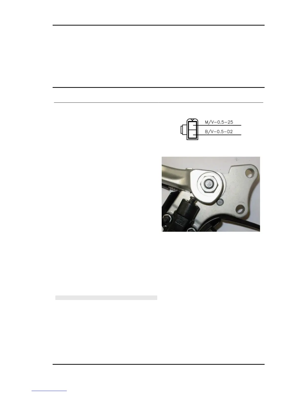
Location:
•
on the vehicle: on the stand
•
connector: between head cover and fil-
ter box on left side (2-ways white con-
nector)
Pin out:
1. Ground connection
2. Voltage 12V
Electrical characteristics:
•
Side Stand Up: closed circuit (continu-
ity)
•
Side Stand Down: open circuit (infinite
resistance)
CAUTION
BEFORE CARRYING OUT ANY TROUBLESHOOTING,
CAREFULLY READ THE GENERAL TROUBLESHOOTING
CONCEPTS FOR ELECTRICAL DEVICES AT THE BEGIN-
NING OF THE CHECK AND CONTROL SECTION IN THE
ELECTRICAL SYSTEM CHAPTER.
DIAGNOSIS INSTRUMENT: STATUSES
Side stand sensor: up/down
RSV4 R Electrical system
ELE SYS - 203

 Loading...