Level in wiring diagram:
Exhaust valve
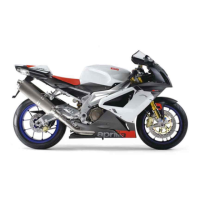
Location:
•
on the vehicle: The motor is placed in
the front lower part of the engine. The
valve in the exhaust duct.
•
connector: on the motor.
Electrical characteristics:
•
Electrical motor resistance (PIN 4-5):
2--4 Ohm
•
Potentiometer resistance (PIN 1-3):
10.1 kOhm +/- 10%
Pin out:
1. Power supply voltage 5V
2. Output signal (0- 5V)
3. Ground connection
4. Motor A supply
5. Motor B supply
DIAGNOSIS INSTRUMENT: PARAMETERS
Exhaust valve target position: 7 - 93 %
NOTE: Value that control unit sends to the instru-
ment panel to activate the valve: 7% (closed
valve), 93 % (open valve).
CAUTION
BEFORE CARRYING OUT ANY TROUBLESHOOTING,
CAREFULLY READ THE GENERAL TROUBLESHOOTING
CONCEPTS FOR ELECTRICAL DEVICES AT THE BEGIN-
NING OF THE CHECK AND CONTROL SECTION IN THE
ELECTRICAL SYSTEM CHAPTER.
DIAGNOSIS INSTRUMENT: STATUSES
Exhaust valve
•
Indefinite/in research/activation with key ON/ in operation/stopped for detected malfunction/
research of zero position.
NOTE: If there is no problem, it appears: in operation
DIAGNOSIS INSTRUMENT: ELECTRICAL ERRORS
Exhaust valve stop research P0191
•
potentiometer signal above maximum threshold/potentiometer signal below minimum
threshold/excessive time/research not carried out or wrong stroke.
Error cause
Electrical system RSV4 R
ELE SYS - 210

 Loading...