•
Key switch connector
•
Immobilizer aerial connector
•
Oxygen sensor connector
•
Output "30" engine revolution sensor connector
•
Outputs "25" and"26" 7SM control unit connectors
•
Outputs "29", "8", "7" and "28" coil connectors
•
Output "15" gear sensor connector
•
Output "11" secondary air solenoid connector
•
Output "13" front motorised throttle body connector
•
Output "14" rear motorised throttle body connector
•
Outputs "11" and "27" MAP sensor connectors
•
Outputs "20", "21", "22" and "23" upper injector connectors
•
Outputs "5", "6", "16" and "17" lower injector connectors
The connectors in the list are circled in the different pictures. The listed connectors are con-
sidered more critical than the others because their disconnection could cause the vehicle to
stop or malfunction.
Obviously, the correct connection of the other connectors is also important and essential for proper
vehicle operation.
It is also important and essential that the instructions regarding the routing and fixing of the cable har-
ness in the various areas are followed meticulously in order to guarantee functionality and reliability.
Front side
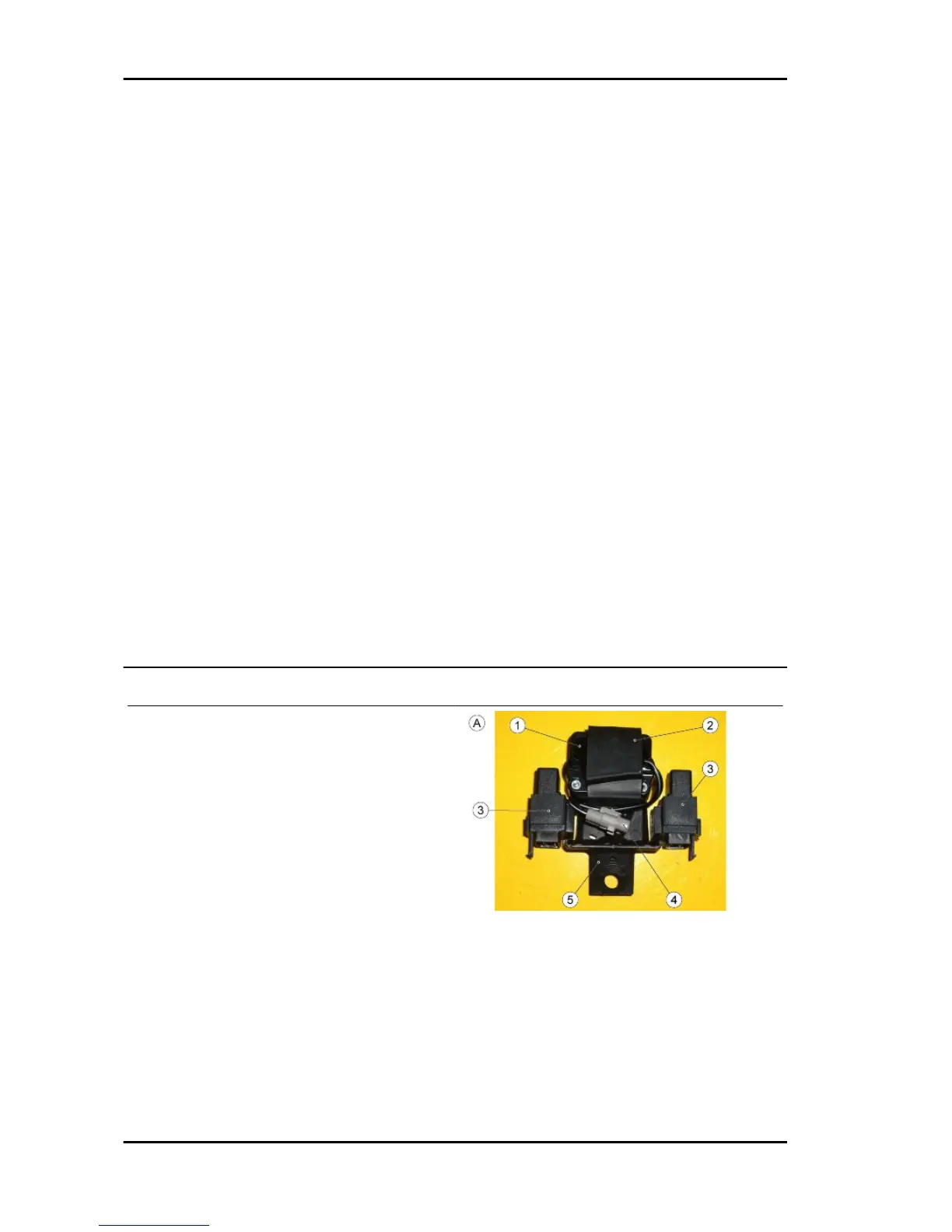
TABLE A - RELAY AND FALL SENSOR
MOUNTING PRE-FITTING
Check that the fall sensor has been positioned
correctly, with the arrow above the indication UP-
PER facing upward.
1. fall sensor
2. Fall sensor rubber ring
3. Relay
4. Fall sensor connector
5. Mounting
TABLE B - REGULATOR PRE-FITTING
6. Regulator
7. Regulator connector
8. Flywheel connector
9. Self-locking nut (x2)
10. T-shaped bushing (x2)
Electrical system RSV4 R
ELE SYS - 100

 Loading...