•
Indication on Axone always Normal, even when the sensor is inverted: disconnect the con-
nector and, with sensor inverted, check if there is continuity between the two PINS of the
sensor: If there is not continuity, replace the sensor; if there is continuity, check the con-
nector: if not OK, restore cable harness; if OK, check the ground continuity of PIN 1: if there
is not continuity, restore cable harness; if there is continuity, check, with key ON, if there is
voltage of 5 V at PIN 2; if there is not voltage, check Marelli control unit connector (with
special attention to PIN 65) and check the vehicle-engine cable harness connector (with
special attention to PIN B6).
•
Indication on Axone always Tip over: disconnect the connector and check if there is con-
tinuity between the two PINS when the sensor is in vertical position: if there is continuity,
replace the sensor; if there is not, it means that, with key set to ON, there is no 5V voltage
at PIN 2: restore the cable harness whose pink/white cable will be shorted to ground
CAUTION
BEFORE CARRYING OUT ANY TROUBLESHOOTING, CAREFULLY READ THE GENERAL TROU-
BLESHOOTING CONCEPTS FOR ELECTRICAL DEVICES AT THE BEGINNING OF THE CHECK
AND CONTROL SECTION IN THE ELECTRICAL SYSTEM CHAPTER.
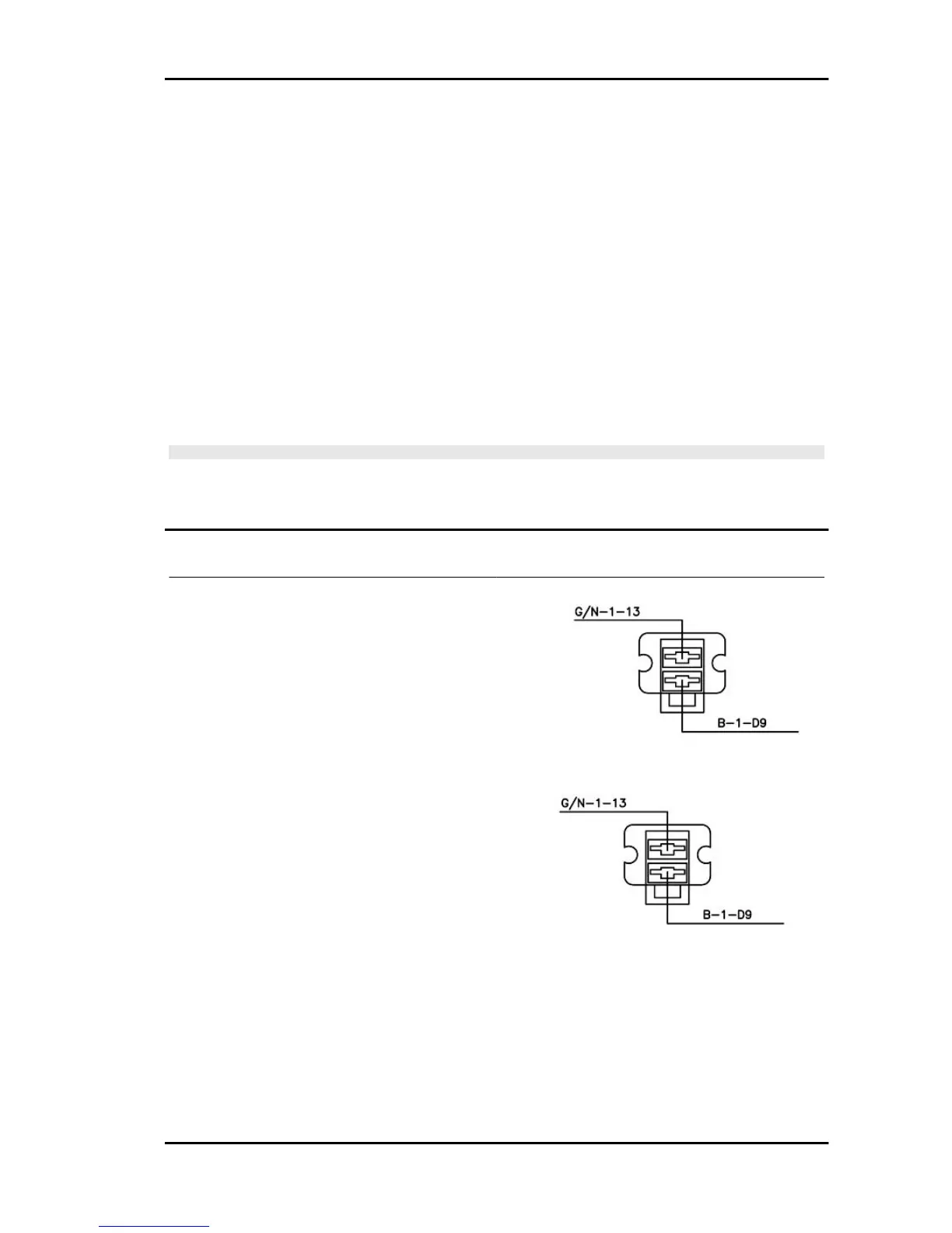
Electric fan circuit
Function
Radiator fan and coolant - Operation
Operation / operating principle
When the control unit detects a temperature of ap-
prox. 101 °C, it closes the fan control relay pickup
circuit to ground
Level in wiring diagram:
electric fan
Location:
•
sensor: relay placed in the frame front
niche, on the left
•
connector: on the relay
Electrical characteristics:
•
relay normally open;
•
drive coil resistance 110 Ohm (+/- 10
%)
DIAGNOSIS INSTRUMENT: STATUSES
Fan relay
•
on/off
RSV4 R Electrical system
ELE SYS - 205
 Loading...