Variable geometry intake
(IF AVAILABLE)
Function
Extend or shorten the engine inlet ducts to in-
crease the inlet air quantity according to the engine
revs.
Operation / operating principle
The system consists of:
•
two inlet ducts for each manifold, which
may be joined (long ducts) or separa-
ted (short ducts);
•
a motor that, by means of an endless
screw, activates the upper part of the
inlet ducts;
•
a variable geometry control unit for
managing the system, interfaced with
the engine injection control unit.
At key-ON, the variable geometry control unit low-
ers the ducts (if still in the raised position). Subse-
quently, depending on the control voltage on PIN
2 from the injection control unit (0V down, 5V up),
the control unit drives the electric motor with the
relative polarity for raising or lowering the ducts.
The drive voltage delivered to the motor is deter-
mined in relation to battery voltage and the motor
is stopped once a given current limit is reached or
if the time-out period of 500 ms has elapsed.
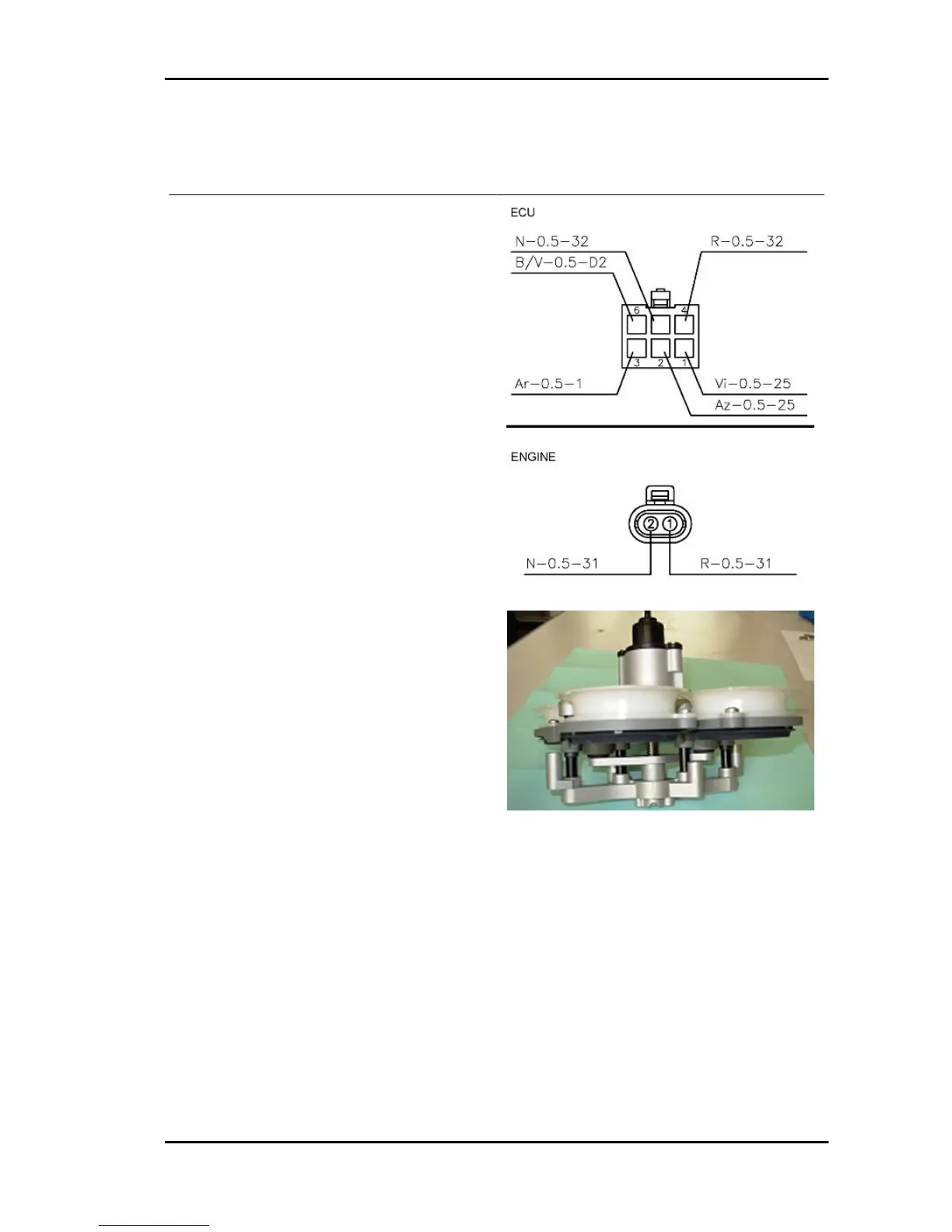
Level in wiring diagram:
Variable geometry
Location:
•
on the vehicle: ducts and motor inside
the filter box, variable geometry control
unit on rear frame under the saddle,
right side.
•
variable geometry control unit connec-
tor: on the control unit.
RSV4 R Electrical system
ELE SYS - 151
 Loading...