replace the sensor (there is short circuit to ground of the pink cable in the section from the
sensor connector to the sensor or inside the sensor).
Clutch lever sensor
Function
It tells the clutch lever position to the control unit.
Operation / operating principle
If there is gear engaged but the clutch is pulled, i.e.
circuit closed to ground, vehicle start-up is not en-
abled.
Level in wiring diagram:
Start-up enabling switches
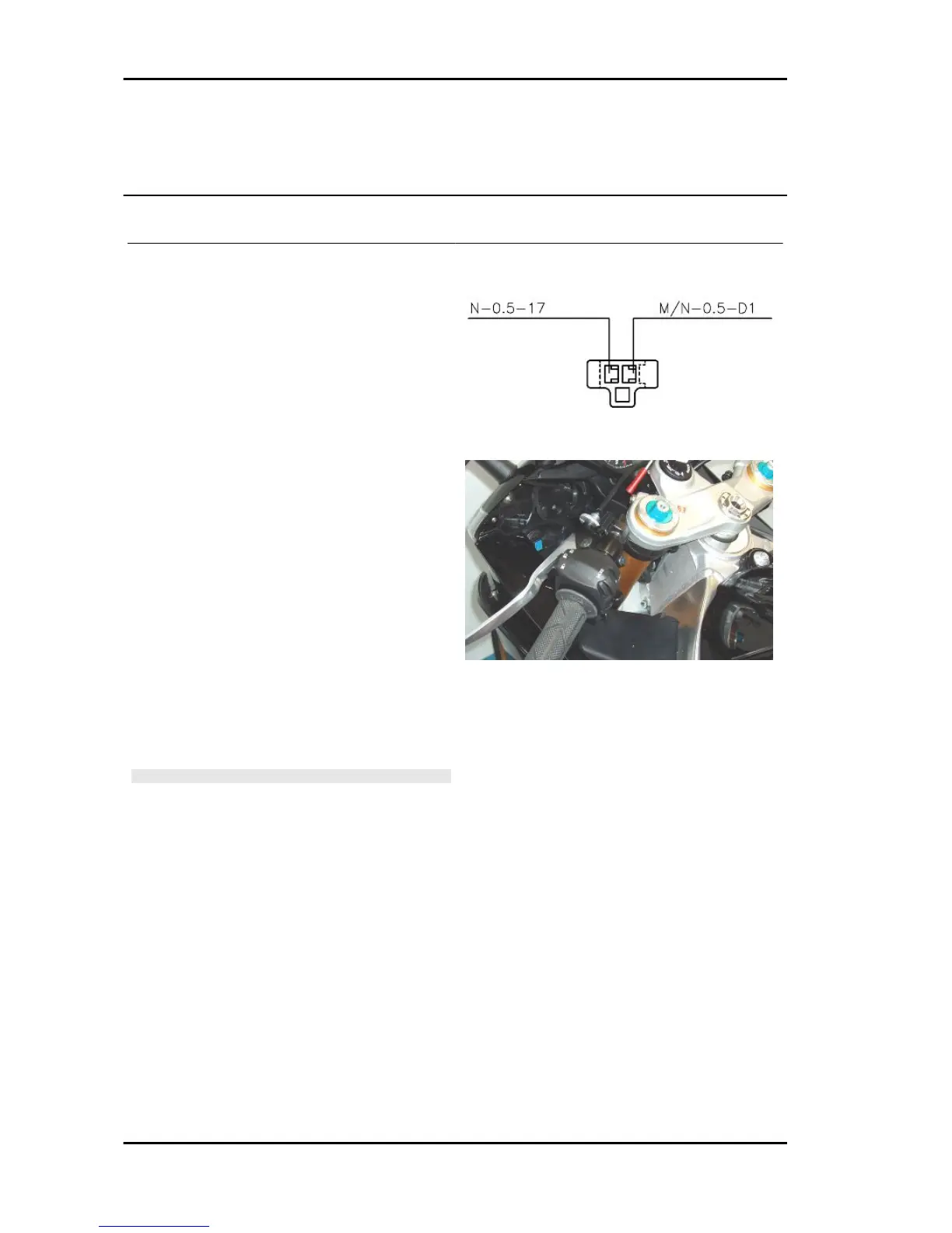
Location:
•
on the vehicle: on the handlebar.
•
connector: on the sensor.
Electrical characteristics:
•
Clutch pulled: closed circuit (continui-
ty)
•
Clutch released: open circuit (infinite
resistance).
Pin out:
1. voltage 5V
2. ground connection
CAUTION
BEFORE CARRYING OUT ANY TROUBLESHOOTING,
CAREFULLY READ THE GENERAL TROUBLESHOOTING
CONCEPTS FOR ELECTRICAL DEVICES AT THE BEGIN-
NING OF THE CHECK AND CONTROL SECTION IN THE
ELECTRICAL SYSTEM CHAPTER.
DIAGNOSIS INSTRUMENT: STATUSES
Clutch
•
Indefinite_Released_Pulled
WARNING The statuses regularly viewed are Released and Pulled.
•
Indication on Axone always Released: check the sensor connector, the engine-vehicle cable
harness connector (special attention to PIN C3) and the control unit connector (special at-
tention to PIN56): if not OK, restore cable harness; if OK, disconnect both terminals from
the sensor and check, with key set to ON, continuity to ground of PIN 2: if there is no con-
tinuity, restore the cable harness; if there is, replace the sensor.
Electrical system RSV4 R
ELE SYS - 202

 Loading...