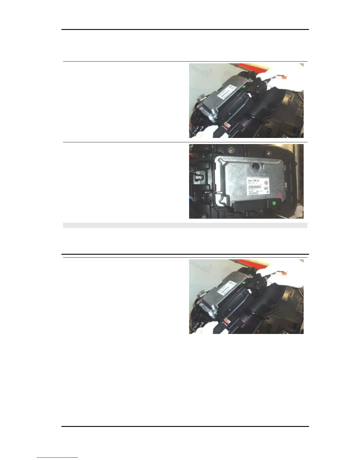
Control unit
Removal
•
Remove the fuel tank.
•
Disconnect both control unit connec-
tors
•
Unscrew and remove the three screws.
•
Remove the control unit.
NOTE
WHEN REFITTING THE CONNECTORS, THE SLIDES MUST MOVE FREELY TO THE END OF
STROKE, WHICH HELPS WITH THE INSERTION OF THE CONNECTOR: YOU MUST HEAR THE
RELEASE OF THE RETAINING TANG AT THE END OF STROKE.
CONTROL UNIT - Diagnosis
Function
it controls the Ride by wire system, the injection/
ignition, the system safety checks and the self-di-
agnosis function
Level in wiring diagram:
Each level in which the main component involves
the control unit
Location:
•
on the vehicle: above the filter box
•
connector: on connector control unit of
ENGINE PIN 52 (figure A), connector
of ENGINE PIN 28 (figure B)
Pin out:See the CONNECTORS section
DIAGNOSIS INSTRUMENT: PARAMETERS ISO
Screen page
RSV4 R Electrical system
ELE SYS - 143
 Loading...