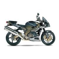
TABLE ZB - H2O TEMPERATURE SENSOR
114. Cable harness routing (branch "4") under the
3-way fitting
115. Engine speed sensor cable routing between
the front motorised throttle body and the 3-way fit-
ting
116. Rubber clamp
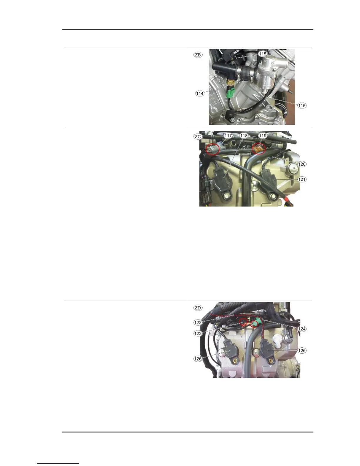
TABLE ZC
At this point, the injectors 2 (output "5") and 4 (out-
put "6") can be connected: the connector (117) for
injector 4 is GREY (or there is a spot with grey tape
on the cable harness) whereas the connector
(119) for injector 2 is BROWN.
Move the connector for coil 2 (output "7"), marked
with red tape, to the far left, routing with the re-
spective wiring together with the injector cable
harnesses.
117. Lower injector 4 cable harness connector
(output "6") - grey connector
118. Coil 4 - short cable harness
119. Lower injector 2 cable harness connector
(output "5") - brown connector
120. Coil 2 cable harness routing (output "7")
121. Coil 2 - long cable harness
TABLE ZD
Connect the injectors 1 (output "16") and 3 (output
"17"), which are on branch "3": the connector (123)
for injector 1 is BLACK whereas the connector
(124) for injector 3 is GREEN (or there is a spot
with blue tape on the cable harness).
Move the cable for coil 3 to the far left, routing it as
shown in the following figure (122).
122. Coil 3 cable routing
123. Lower injector 1 cable harness connector
(output "16") - black connector
RSV4 R Electrical system
ELE SYS - 119
 Loading...