4 000000 000000 000000 000000 Drop
fc1/2 - Target1 interface
Entry# Source ID Mask Destination ID Mask Action
1 010002 ffffff 010001(host) ffffff Permit
2 000000 000000 000000 000000 Drop
fc1/3 - Target2 interface
Entry# Source ID Mask Destination ID Mask Action
1 010003 ffffff 010001(host) ffffff Permit
2 000000 000000 000000 000000 Drop
fc1/4 - Target3 interface
Entry# Source ID Mask Destination ID Mask Action
1 010004 ffffff 010001(host) ffffff Permit
2 000000 000000 000000 000000 Drop
Note that in the above example, the target-to-target entries are not found, and that six of the 12 entries are no
longer programmed. This results in lesser use of TCAM and better security (only the host can communicate
with the three targets, and the targets themselves can communicate only with one host, and not with each
other).
Forwarding Engines
TCAM is allocated to individual forwarding engines and forwarding engines are assigned a group of ports.
Director-class Fibre Channel modules have more TCAM space than fabric switches. The number of forwarding
engines, the ports assigned to each forwarding engine, and the amount of TCAM allocated to each forwarding
engine is hardware dependent.
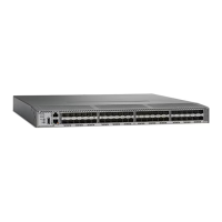
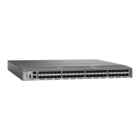
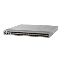
The following example shows an output from Cisco MDS 9148S:
RTP–SAN–15–10–9148s–1# show system internal acltcam–soc tcam–usage
TCAM Entries:
=============
Region1 Region2 Region3 Region4 Region5 Region6
Mod Fwd Dir TOP SYS SECURITY ZONING BOTTOM FCC DIS FCC ENA
Eng Use/Total Use/Total Use/Total Use/Total Use/Total Use/Total
––– ––– –––––– –––––––––– ––––––––– –––––––––––– ––––––––– ––––––––– –––––––––
1 1 INPUT 19/407 1/407 1/2852 * 4/407 0/0 0/0
1 1 OUTPUT 0/25 0/25 0/140 0/25 0/12 1/25
1 2 INPUT 19/407 1/407 0/2852 * 4/407 0/0 0/0
1 2 OUTPUT 0/25 0/25 0/140 0/25 0/12 1/25
1 3 INPUT 19/407 1/407 0/2852 * 4/407 0/0 0/0
1 3 OUTPUT 0/25 0/25 0/140 0/25 0/12 1/25
–––––––––––––––––––––––––––––––––––––––––––––––––––
* 1024 entries are reserved for LUN Zoning purpose.
The above example indicates the following:
• There are three forwarding engines, 1 through 3.
• Since there are 48 ports on Cisco MDS 9148 switches, each forwarding engine handles 16 ports.
• Each forwarding engine has 2852 entries in region 3 (the zoning region) for input. This is the main region
used, and consequently, has the largest amount of available entries.
• Forwarding engine 3 has only one entry that is currently in use out of the total 2852 in the zoning region.
The following example shows the output from Cisco MDS 9710 switch with a 2/4/8/10/16 Gbps Advanced
Fibre Channel Module (DS–X9448–768K9):
F241–15–09–9710–2# show system internal acl tcam–usage
Cisco MDS 9000 Series Fabric Configuration Guide, Release 8.x
141
Configuring and Managing Zones
Forwarding Engines
 Loading...


