VSANs Topologies
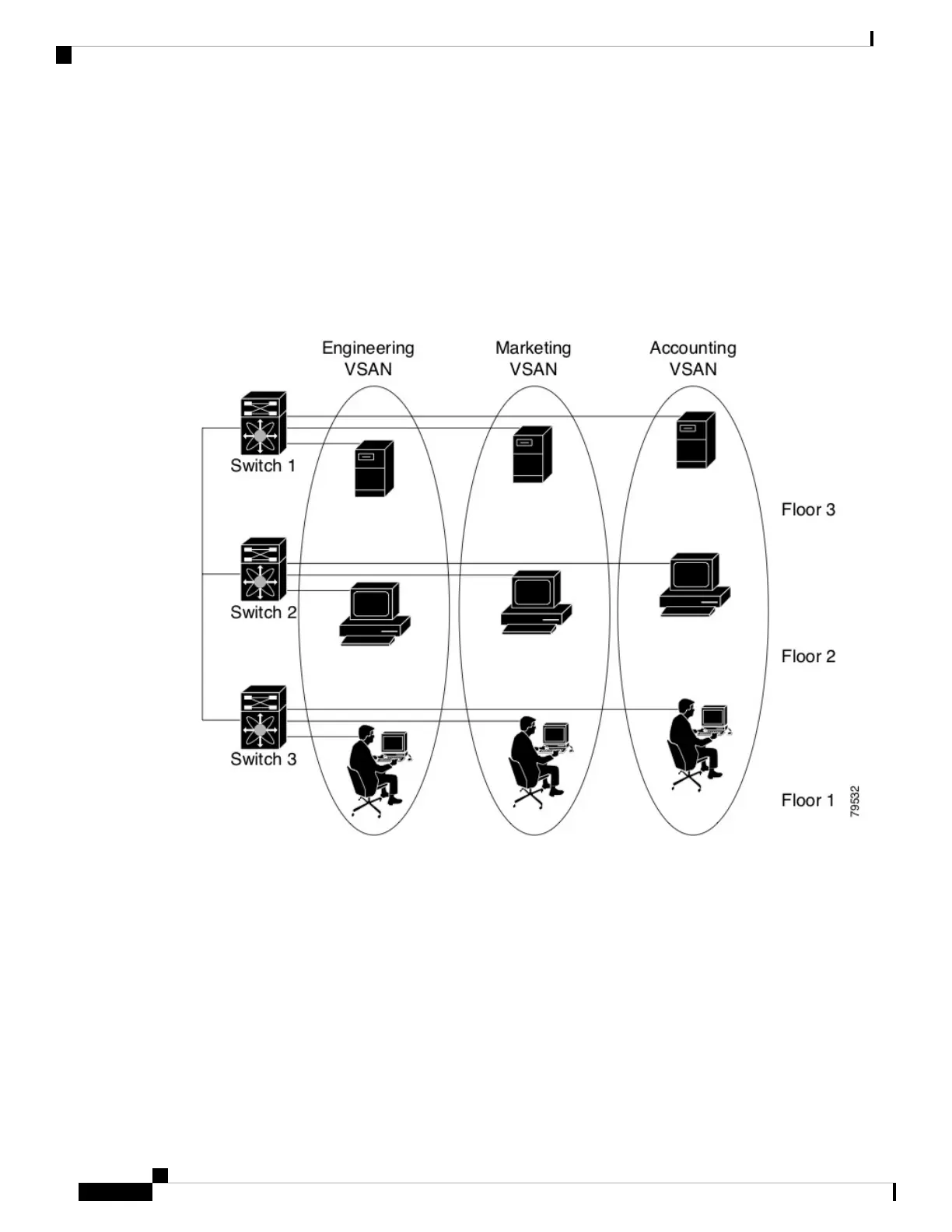
The switch icons shown in both Figure 1: Logical VSAN Segmentation, on page 8 and Figure 2: Example
of Two VSANs, on page 9 indicate that these features apply to any switch in the Cisco MDS 9000 Family.
Figure 1: Logical VSAN Segmentation, on page 8 shows a fabric with three switches, one on each floor.
The geographic location of the switches and the attached devices is independent of their segmentation into
logical VSANs. No communication between VSANs is possible. Within each VSAN, all members can talk
to one another.
Figure 1: Logical VSAN Segmentation
Figure 2: Example of Two VSANs, on page 9 shows a physical Fibre Channel switching infrastructure with
two defined VSANs: VSAN 2 (dashed) and VSAN 7 (solid). VSAN 2 includes hosts H1 and H2, application
servers AS2 and AS3, and storage arrays SA1 and SA4. VSAN 7 connects H3, AS1, SA2, and SA3.
Cisco MDS 9000 Series Fabric Configuration Guide, Release 8.x
8
Configuring and Managing VSANs
VSANs Topologies

 Loading...