This example assumes that the port channel (PC) contains 8 interfaces, fc1/1-fc1/8.
In addition, the following two zones are active:
zone1
member host (host 0x010001)
member target1 (target1 0x010002)
zone2
member host (host 0x010001)
member target2 (target2 0x010003)
In such a scenario, the following ACL programming will be present on each member of the PC:
fc1/1(through fc1/8) (port-channel)
Entry# Source ID Mask Destination ID Mask Action
1 010001 ffffff 010002(target1) ffffff Permit
2 010001 ffffff 010003(target2) ffffff Permit
3 000000 000000 000000 000000 Drop
The above example shows the ACL TCAM programming that will be duplicated on each member of the F
port-channel. Consequently, if a lot of programming is required because of a large number of FLOGIs on the
F port channel, or a large number of devices are zoned with the devices on the F port channel, TCAM can be
exhausted on a forwarding engine. The following are the best practices for efficient use of TCAM with respect
to F ports and F port-channels:
• Distribute port-channel member interfaces into different forwarding engines, especially on fabric switches.
• If TCAM usage is still too high in the case of port-channel with a large number of interfaces, then split
the port-channel into two separate port-channels each with half the interfaces. This will still provide
redundancy but will reduces the number of FLOGIs per individual port-channel and thus reduce TCAM
usage.
• Distribute member interfaces into different linecards on director-class switches.
• Distribute member interfaces into forwarding engines with lower TCAM zoning region usage.
• Use single-initiator zones, single-target zones, or Smart Zoning.
E and TE Port Channels and IVR
E port channels provide Inter Switch Links (ISLs) between fabric switches. Typically, there is minimal TCAM
programming on these types of interfaces. Therefore, besides placing them into different linecards, and perhaps
port groups on director-class switches, there is a little more to be done. However, when the Inter VSAN
Routing (IVR) feature is being deployed, extensive TCAM programming can exist on ISLs because the IVR
topology transitions from one VSAN to another. Consequently, most of the considerations that apply on F/TF
port channels will be applicable here too.
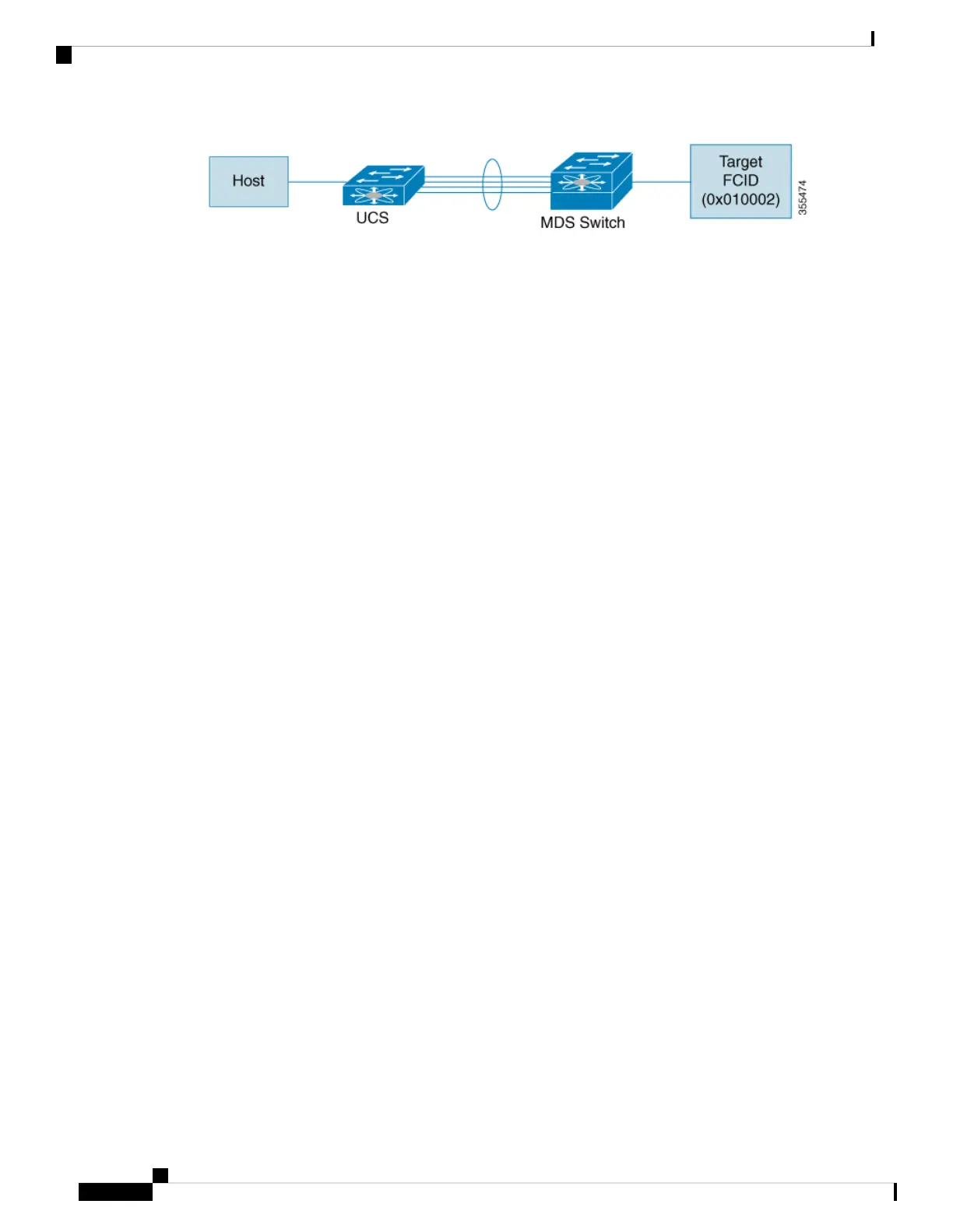
The following is an example of a topology:
Cisco MDS 9000 Series Fabric Configuration Guide, Release 8.x
146
Configuring and Managing Zones
E and TE Port Channels and IVR

 Loading...