A53 Z0 9 0020 L En Technical documentation
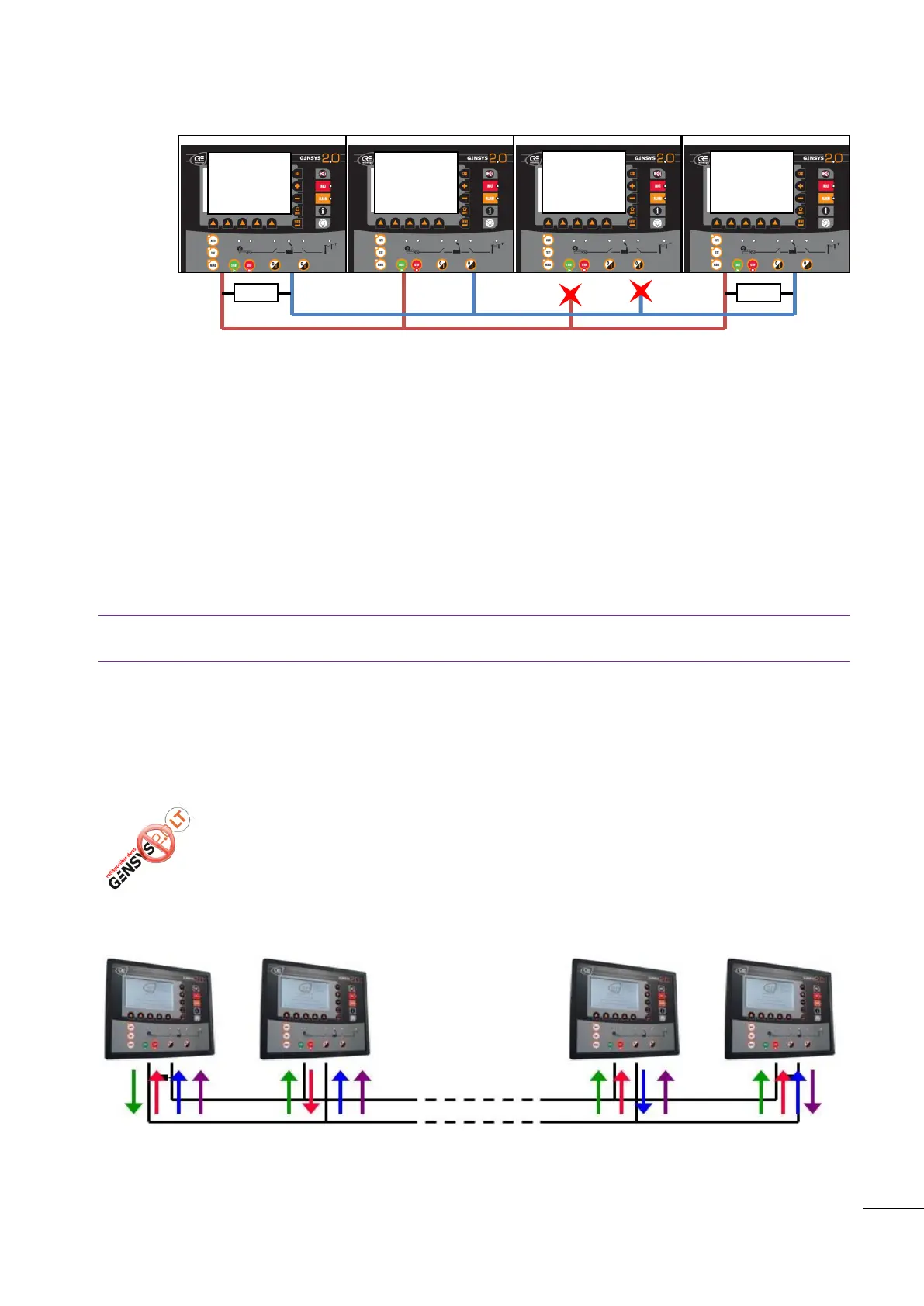
Figure 77- Example CAN bus fault
If a remote start occurs on a GENSYS 2.0 working in automatic mode and set up to manage Deadbus
situations (E1515 = 0) and a CAN bus fault has already been triggered, GENSYS 2.0 will start its engine and
close its breaker (if there is no voltage on the bus bar) after a delay that depends on the generator number
[E1179]. If there is a voltage on the bus bar, GENSYS 2.0 will synchronize the generator before connecting
to the bus bar.
If the generator is paralleled to the Mains when a CAN bus fault occurs, and error control variable [E1259]
is set to 6 (Droop mode + Alarm), speed control will be switched to droop and volt control will be switched
to power factor regulation. If the Mains are not connected, both speed and voltage droop is applied.
Note: If you need to disconnect a GENSYS 2.0 from the inter GENSYS 2.0 CAN bus, you must change the
number of generators (parameter E1147) on all other GENSYS 2.0 units of the power plant.
When the power plant is set to load/unload mode (Parameter [E1258] set to "Hours run" or "GE number"),
all generators will start using droop mode if a CAN bus error occurs.
15.2.2
Broadcasting data between multiple units
Figure 78 -Broadcasting data between multiple units
Custom data can be sent from one unit to the others using simple custom equations. This
is very useful to create your own advanced features and adapt your modules to your very
specific requirements. It is possible to send up to 10 digital variables and 2 analogue
variables from one CRE Technology unit to all other units connected to the same inter
module CAN bus (COM 1).
01 : 1200 kW
02 : 1000 kW
03 :
04 : 1200 kW
01 : 1200 kW
02 : 1000 kW
03 :
04 : 1200 kW
01 : 1200 kW
02 : 1000 kW
03 :
04 : 1200 kW
01 :
02 :
03 : 1400 kW
04 :

 Loading...