EasyManua.ls Logo

CRE Technology GENSYS 2.0 - Generator Paralleling with Digital Bus; Figure 21 - Power Plant with Several Generators; Table 11 - Typical Basic Multi Generator Configuration

CRE Technology GENSYS 2.0
244 pages
To Next Page IconTo Next Page
To Previous Page IconTo Previous Page
Loading...
A53 Z0 9 0020 L En Technical documentation
Chapter : Predefined configuration
52
8.3
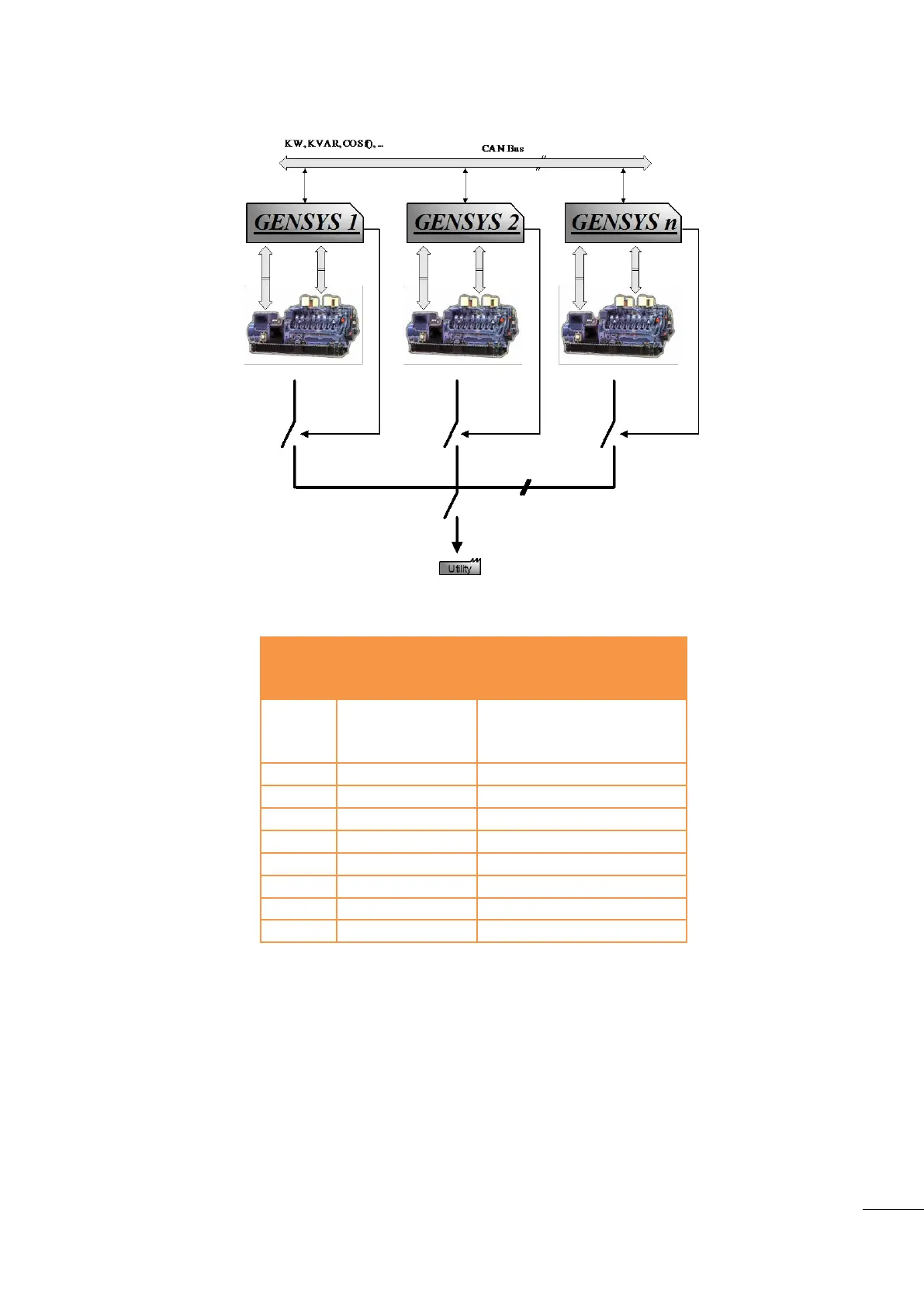
Generator paralleling with digital bus
Figure 21 - Power plant with several generators
Variable
number
Variable label
Variable value
1179
My Number
1 to 32 : this value must be
different for each device on
the same bus
1147
Nb. of gen.
2 ≤ N ≤ 32
4006
Nb. of Master
0
1148
Mains parallel
NoCh.over
1153
Mains regul.
X
1158
Load sharing
Bus CAN
1177
Static paralleling
No
1515
DeadBus manag.
Yes
1258
Load/Unl. mode
X
Table 11 - Typical basic multi Generator configuration
In this mode, CAN bus on COM1 “inter GENSYS 2.0" is used to manage the different units on the same bus.
This mode has better reliability and accuracy than equivalent analogue solutions.

Table of Contents

Related product manuals