A53 Z0 9 0020 L En Technical documentation
Chapter : Dedicated I/O lines
-2Hz and
+0,8Hz
(although the
GENSYS 2.0
output still
increase)
G2(speed
input line)
915
G2
D2(sensor
return)914
5V(ref
speed) 999
Two different
wirings for the
same governor.
Table 18 - Speed governor parameters
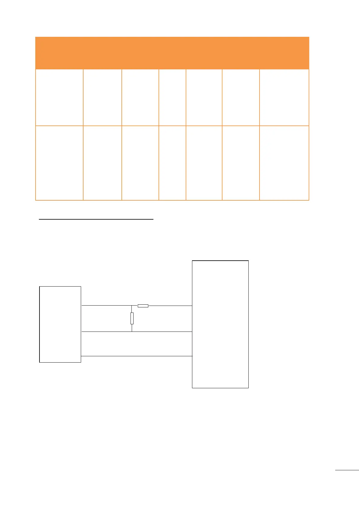
Connecting GENSYS 2.0 to a Cummins EFC:
Because of the very high sensitivity of Cummins EFC module input, please use the schematic below to
connect your GENSYS 2.0 to the EFC. The resistors must be as close as possible of the speed governor
terminal. This way, GENSYS 2.0 analogue speed output can be set higher (parameter E1076) according to
the resistors used.
Gensys2.0
Speed
governor
EFC Cummins
15k
1.5k
speed out
speed ref
G9 (Speed Out)
G11 (Speed Ref)
speed input
8
9
K3 (0v)
2 ( battery - )
Figure 41 – Connection with EFC Cummins
10.1.2
PWM 500 Hz (caterpillar/perkins)
K4 output is a 500Hz PWM output signal between 0 and 5V. It is protected against short-circuits between
the output and the battery negative voltage. To activate this PWM output in order to control speed of
Caterpillar or Perkins engines, please check GENSYS 2.0 parameters as shown below.

 Loading...