A53 Z0 9 0020 L En Technical documentation
Chapter : Installing and commissioning a GENSYS 2.0 application
Plug in the connectors.
9.3.2
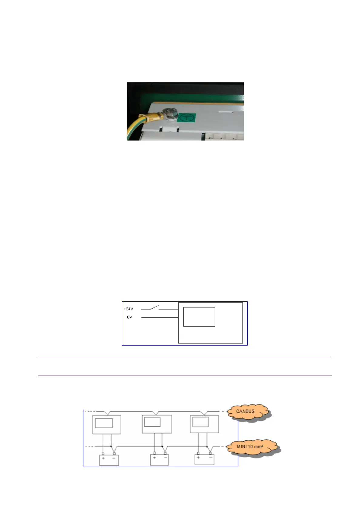
Earth grounding
Earth grounding of the GENSYS 2.0 should be made with two M5 screws & fan washers. Use a short 4mm²
cable to connect the unit to earth (see below).
Figure 37 - Earth grounding
9.3.3 Wiring guidelines
The power cable must be kept separate from the communication cable. The communication cable can be
installed in the same conduit as the low level DC I/O lines (under 10 volts).
If power and communication cables have to cross, they should do so at right angles.
Correct grounding is essential to minimise noise from electromagnetic interference (EMI) and is a safety
measure in electrical installations. To avoid EMI, shield communication and ground cables appropriately.
If several GENSYS 2.0 units are used, each of the 0V power supplies (pin K3) must be connected to each
other with a 4mm² cable (use an adapter for the 2.5mm² connection to the GENSYS 2.0 power connector
itself).
1/ Power supply circuit breaker
Terminal K3 (0V) should never be disconnected. The battery circuit should only be opened using a breaker
placed between the battery's positive terminal and the K2 terminal (Power supply +).
Figure 38 – Power supply circuit breaker
Note: If terminalK3 (0V) is disconnected and the bus bar voltage is applied to the GENSYS 2.0, there is the
risk of getting AC voltage on the CAN bus terminals.
2/ Interconnection of all battery negatives

 Loading...