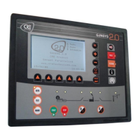
A53 Z0 9 0020 L En Technical documentation
Speed control settings
Recommended if a magnetic pickup can be wired to G7 and
G8 terminals of the GENSYS 2.0
Speed measurement from generator frequency.
Number of teeth on the fly wheel (necessary if "magnetic"
has been chosen as speed measurement source)
Pole pair no.
[E1109]
(2)
Number of pairs of poles on the generator (necessary if
"alternator" has been chosen as speed measurement
source).
Engine idle speed of the internal speed controller; the
engine will accelerate from crank disconnect value to idle
speed; then the speed will increase, following a ramp from
idle speed to nominal speed.
First speed set point (default)
Second speed set point, activated with logical input or
equations.
Droop of the internal speed controller.
Table 93 – Speed control settings configuration
(1) Only available on level 2
(2) Available according to Speed measure [E1078]
(3) Idle speed hould be set to nominal speed 1 value [E1080] if the internal speed controller is not used
Speed governor control
To be set between -100 % for +10V to -10V output to external
speed controller, and 100 % for -10V to +10V output.
This value must be set to have a GENSYS 2.0 control speed
deviation of +/- 3Hz on the engine. (See §10.1.1 for more details)
Voltage on output to external speed controller without correction:
between -100 % for -10V and +100% for +10V.
Display generator frequency in Hz.
Display engine speed in rpm.
Display the speed output value.
Table 94 – Speed governor control configuration

 Loading...