A53 Z0 9 0020 L En Technical documentation
Chapter : Predefined configuration
To allow Power Factor regulation, the "Mains breaker in" (J1) input to GENSYS 2.0 must be connected.
Power Factor regulation is not an option.
8.7.1
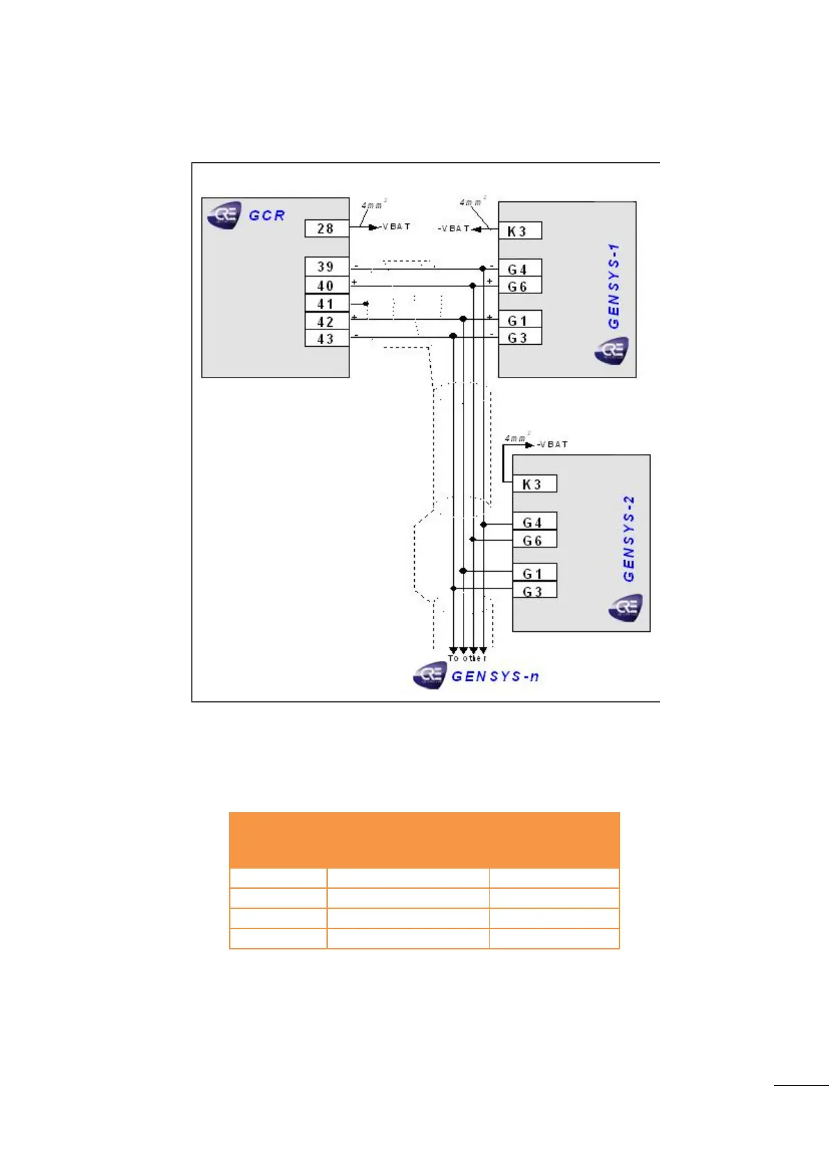
Interfacing GENSYS 2.0 with GCR
Figure 31 - GCR GENSYS 2.0 wiring diagram
GCR (39-40) – GENSYS 2.0 (G4-G6): parallel lines (0-3V) to control active power.
GCR (42-43) – GENSYS 2.0 (G1-G3): mains synchronization bus (+/- 3V).
GENSYS 2.0 (K3): -V
BAT
from speed governor.
Table 16 - GENSYS 2.0 / GCR configuration

 Loading...