A53 Z0 9 0020 L En Technical documentation
Note: Broadcast data are not influenced by the value of these inhibition variables, so it is still possible to
send and receive broadcast values between “inhibited” GENSYS 2.0.
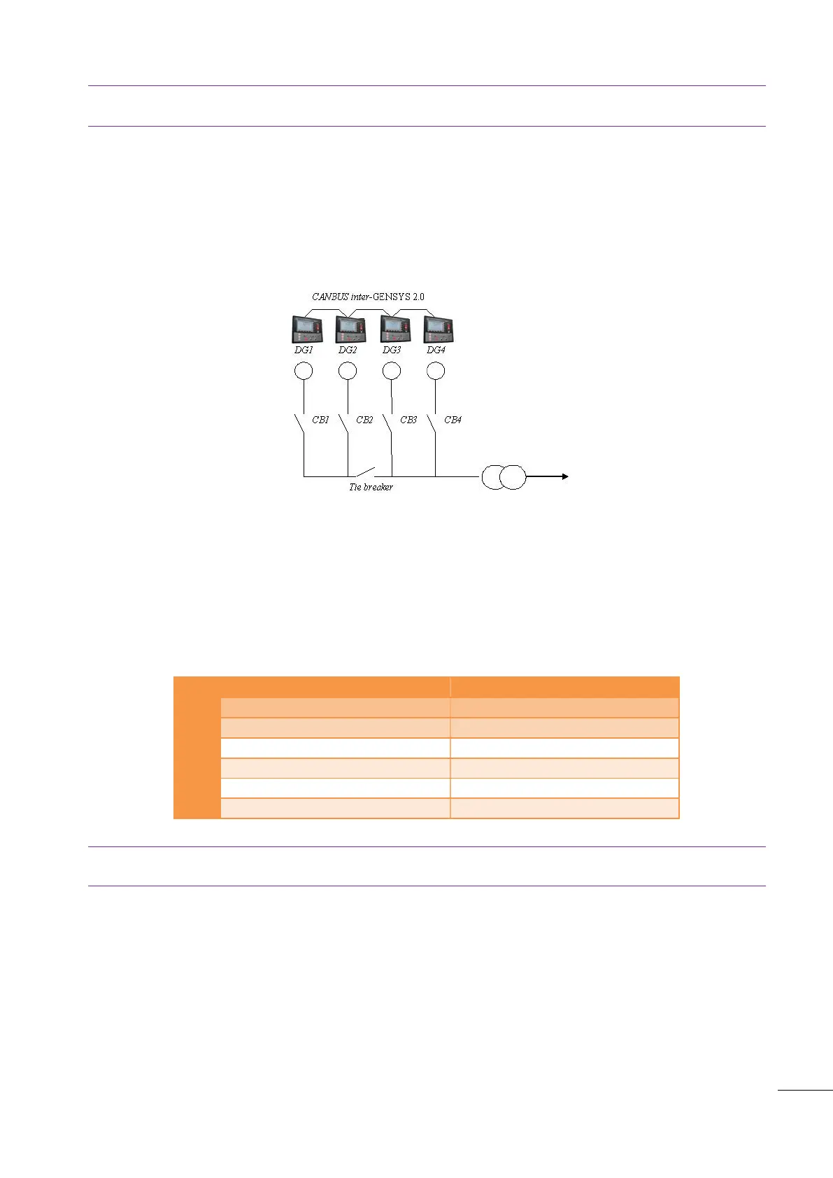
Example below shows a power plant made up of 4 generators that can be split into two power plants of
two generators each. GENSYS 2.0 units are connected together with a CAN bus on COM1. If it is necessary
to split the complete plant using a tie breaker, then it is necessary to modify normal functioning:
When the tie breaker is closed, each GENSYS 2.0 communicates with the 3 other units.
When the tie breaker is open, all GENSYS 2.0 units need to know that they have to consider the
power plant differently, with two separate bus bars. This is where we will use CAN bus inhibition.
Figure 80 - CAN bus inhibition schematic (example)
When the tie breaker is closed, all four GENSYS 2.0 units should communicate with each other for power
management, so variables [E2691] to [E2694] should be set to 0 (zero) on every GENSYS 2.0 unit (no CAN
inhibition). When the tie breaker is open, generators DG1 and DG2 should communicate together but
ignore data coming from DG3 and DG4. In the same way, generators DG3 and DG4 should communicate
together but ignore data coming from DG1 and DG2.
To do so, inhibition variables should be set as shown in table below.
4 generating sets power plant
2 * 2 generating sets power plant
Table 60 - Tie breaker example
Note: In this example, feedback from the tie breaker can be connected to a GENSYS 2.0 digital input and
used in PLC custom equations to set or reset appropriate inhibition variables.

 Loading...