A53 Z0 9 0020 L En Technical documentation
4/ MDEC variables
The following variables are used to communicate with MTU MDEC devices:
-E0330 to E0484 as input variables (MDEC to GENSYS 2.0).
-E2662 to E2677 as output variables (GENSYS 2.0 to MDEC).
The variables from MDEC can be seen from E0330 to E0484.
The variables than can be written in MDEC are available from E2662 to E2677.
The table in the annexes lists all the variables with correspondences between MDEC and GENSYS 2.0.
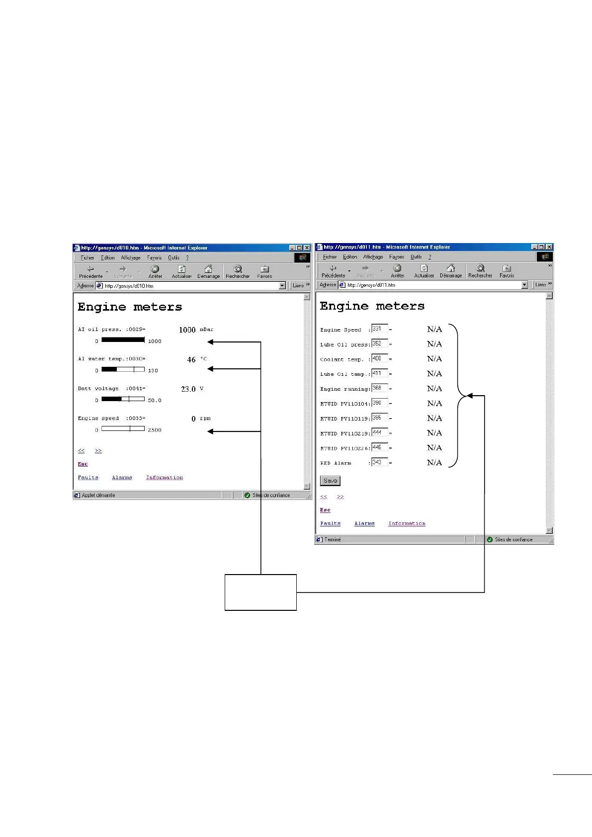
5/ Specific screens for MDEC dedicated pages
Engine monitoring can be done via the “Display/\Engine meters” menu:
Figure 84 – MDEC Screens
6/ Additional information
In the standard configuration GENSYS 2.0 can display all the MDEC variables available on the CAN bus
thanks to the screen seen above. These variables are displayed ‘as is’ without any further processing,
except for certain faults. If you need additional functions related to these variables you will have to
program your own PLC equations.
It is also possible to monitor and manage MDEC variables remotely through MODBUS communication on
GENSYS 2.0 COM5.

 Loading...