A53 Z0 9 0020 L En Technical documentation
15.3.1
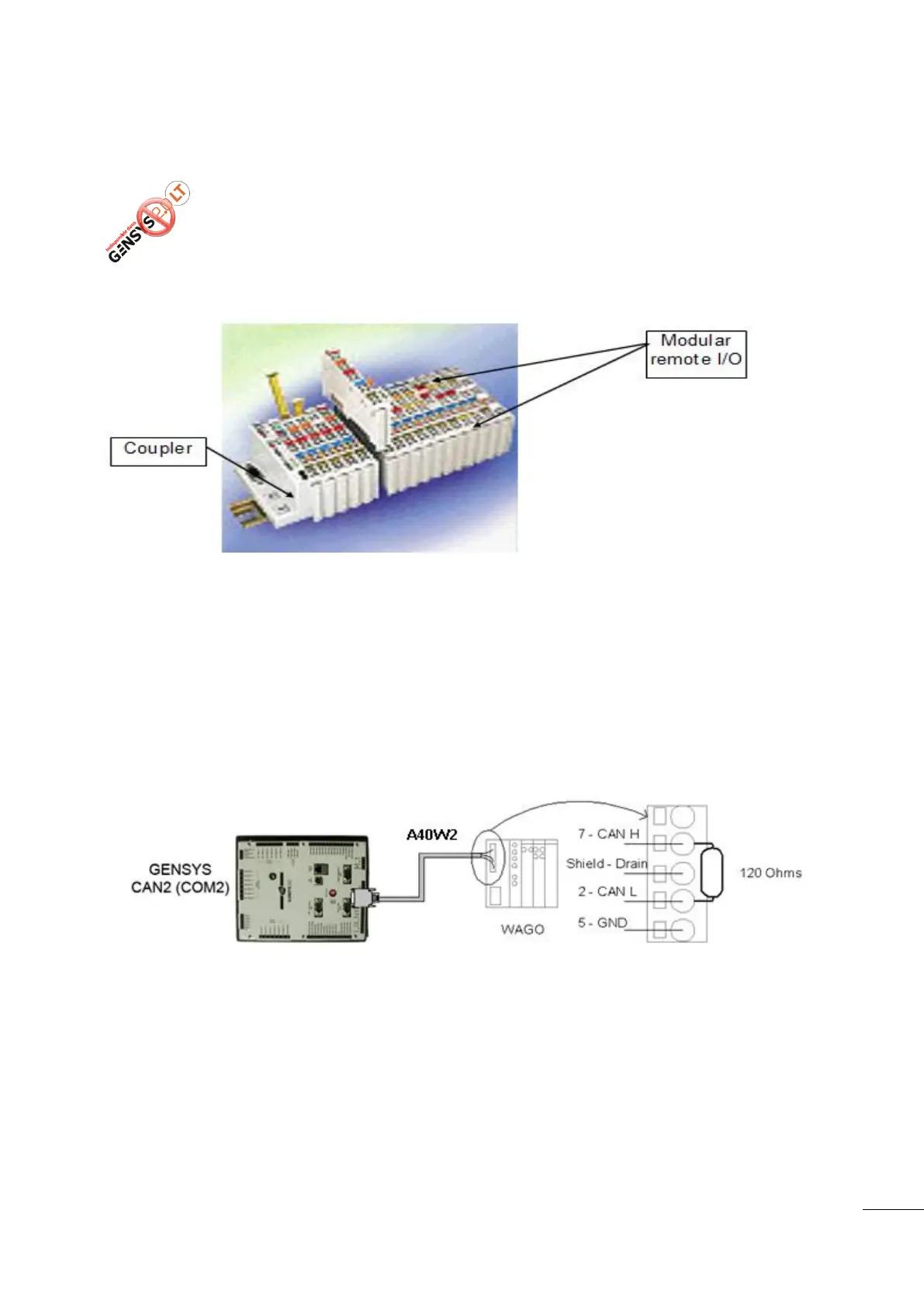
COM2: CANopen communication
Figure 81 - Modular remote CANopen I/O extension module
The refresh rate of these CANopen inputs and outputs is 100ms.
Wiring of the CAN bus on COM2 should be as described in chapter 15.1 CAN bus good practices. Also refer
to the CANopen extension module’s user manual for correct wiring on the CANopen module side.
Modular remote I/O can also be added to GENSYS 2.0 using the CANOPEN© protocol and DB9 connector.
For the remote I/O wiring see the figure below.
Figure 82 - CANopen coupler wiring
CAN L must be connected to pin 2 of the DB9.
CAN H must be connected to pin 7 of the DB9.
CAN GND must be connected to pin 5 of the DB9.
Drain must be connected to the shield of the DB9.
An end resistor of 120 must be connected to each end of the cable between CANH and CANL. This
resistor exists inside GENSYS 2.0 and can be activated with a switch accessible from the rear of the unit and
located under the plug marked “OFF / 120Ω”. COM port is marked on the rear. You need to extract the plug
Industrial CANopen extension modules can be used to increase the number of
digital/analogue inputs and outputs of GENSYS 2.0.

 Loading...