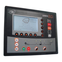
A53 Z0 9 0020 L En Technical documentation
Chapter : Predefined configuration
Loss of voltage
Each GENSYS 2.0 is ordered to start.
All breakers (CB1, CB2, CB3 & CB4) close as ordered by GENSYS 2.0.
DG1, DG2, DG 3, & DG4 start.
All generators reach the speed defined by the [E1896] setting (CANBUS synchronization).
There is a residual voltage of 80V.
All C1outputs close simultaneously to activate excitation (after dialogue between GENSYS 2.0
units).
The nominal voltage is reached immediately at the same time on all generators.
The plant is available to take up required load.
Breakers are closed when engine is stopped.
There is a residual voltage of 80V.
8.5.2
Advantages
Full plant availability in less than 10 seconds.
Gradual magnetization of the step-up transformer (no transient short-circuit).
8.5.3
Configuration
One GENSYS 2.0 per generating set.
CAN bus must be connected between GENSYS 2.0 units.
An "Excitation" output (e.g. exit C1) must be configured on each GENSYS 2.0 unit.
Generator breaker must be powered by 24VDC (so as to close without AC).
In the Setup menu / General Central / sync mode.[ E1177] must be set as "Static stop".
The value of the maximum excitation rpm is set with [E1896] (default: 97%).
The alternators must be identical.
Each GENSYS 2.0 must be equipped with a speed sensor (magnetic sensor / Pick-up).
1 to 32 : this value must be different
for each device on the same bus
Table 13 - Paralleling with mains

 Loading...