A53 Z0 9 0020 L En Technical documentation
Chapter : Dedicated I/O lines
10.3
Analogue AVR (Auto Voltage Regulatior) control
AVR output can be an analogue output, or a digital pulse output. Analogue output is detailed here, digital
pulse output is detailed in §10.2.
AVR control is used to manage Voltage set points, Voltage Synchronization (U=U), KVAR Load sharing and
Power Factor regulation.
To set AVR control correctly:
Start engine in [Manu] mode,
Set Gain E1103:= 0 and Offset E1104:=0 on GENSYS 2.0.
Set the AVR system to 400 VAC using its potentiometer.
Enter maximum correction (E2038 = + 7000) with [Shift] + [+] buttons.
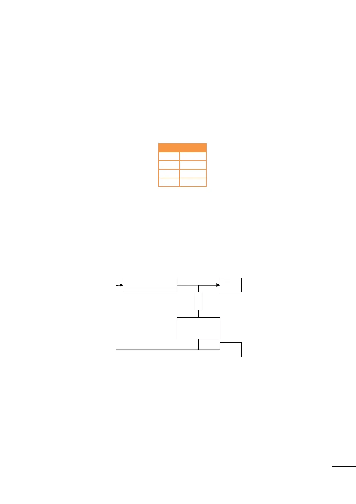
From the following table, choose the best values for Gain and Offset to obtain 430VAC ±5V:
Table 21 - AVR: Gain and offset
If necessary, modify Gain and then Offset to obtain 430VAC ±5.
Enter minimum correction (E2038 = - 7000) with [Shift] + [-] buttons, then check that you have
370VAC ±5
Set to no correction (E2038 = 0) and check that you have 400VAC.
Gain and Offset adjustment if you cannot obtain 400V on the AVR: Adjust the maximum voltage with the
AVR potentiometer, which is normally below 400VAC. Choose the best values for Gain and offset to obtain
the maximum deviation.
Figure 46 - Voltage output

 Loading...