A53 Z0 9 0020 L En Technical documentation
Chapter : Additional functions
13.8
Use of BSM II with GENSYS 2.0
When you have a lot of analogue values to monitor, BSM II can be connected to GENSYS
2.0 to log measurements and process data efficiently. This chapter will explain this type of
configuration.
13.8.1
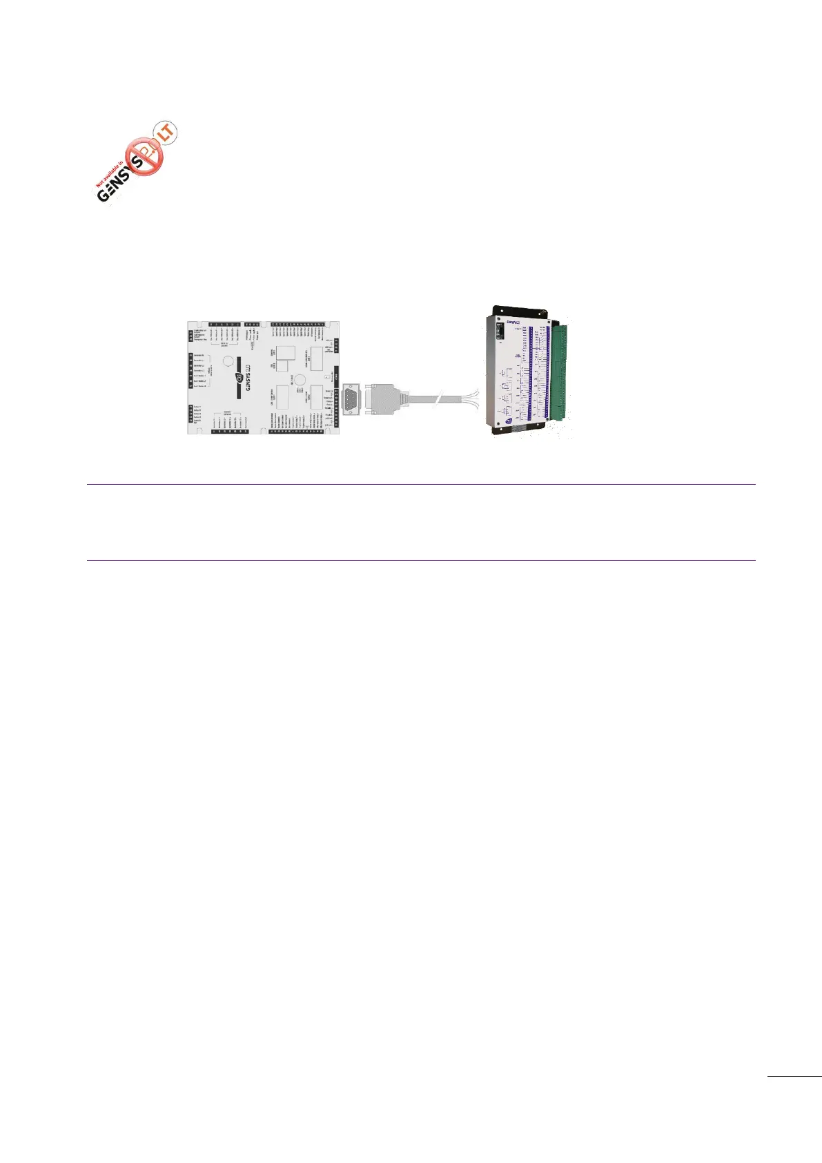
Schematic
Figure 60 - Wiring GENSYS 2.0 to BSM II
Notes:
See §20.3 in order to choose the cable that fit your application.
If BSM II is at the end of the CAN bus, add one 120
resistor in parallel with terminals 5 and 7.
13.8.2
Configuration
The communication between GENSYS 2.0 and BSM II uses a CANopen protocol. BSM II is a slave unit and
GENSYS 2.0 a master unit.
GENSYS 2.0 can be connected to several devices via its COM2: BSM II (Max 2), Wago coupler (Max 32).
Only one of the two BSM II must be set to log data from GENSYS 2.0 (limited by the number of messages
sent from GENSYS 2.0).
13.8.3
Procedure example
This example allows you to log the most significant variables of your application when an alarm occurs.
See also the application note “A43Z090100A” to configure the BSM II logging.
Download the text file (level 1 equation) “Z090211a_1.txt” to the GENSYS 2.0 as described in §15.7.3 or
§17.4.7.
Download the text file (level 1 equation) “A43Z090100a_1.txt” to the BSM II.
Archiving of data begins immediately.
Variables are stored in the BSM II at the rate of 1 sample per second when an alarm occurs:
5 samples before the alarm
1 sample when alarm occurs
5 samples after the alarm
GENSYS 2.0
CAN2
(COM2)
120 Ω active
if end of bus
BSMII
5 CANH ; 7
CAN L + R 120
Ω

 Loading...