A53 Z0 9 0020 L En Technical documentation
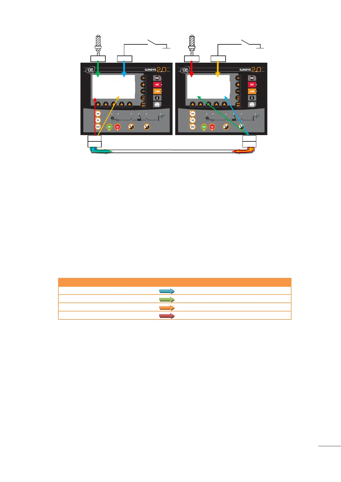
Figure 79 - Analogue and digital data broadcast example
To send desired data on CAN bus the following equations should be used on both GENSYS 2.0 units:
BLOC
@Send input J6 on CAN bus using first digital broadcast data;
X2752:=2806;
@Send engine speed on CAN bus using first analogue broadcast data;
X2762:=33
BEND
Following table lists variables used in GENSYS 2.0 to store data coming from the other unit.
GENSYS 2.0 #1 – digital input J6
Stored in E0536 of GENSYS 2.0 #2
GENSYS 2.0 #1 – engine speed
Stored in E0546 of GENSYS 2.0 #2
GENSYS 2.0 #2 – digital input J6
Stored in E0552 of GENSYS 2.0 #1
GENSYS 2.0 #2 – engine speed
Stored in E0562 of GENSYS 2.0 #1
Table 58 - Analogue and digital data broadcast example

 Loading...