A53 Z0 9 0020 L En Technical documentation
Chapter : Dedicated I/O lines
10.2
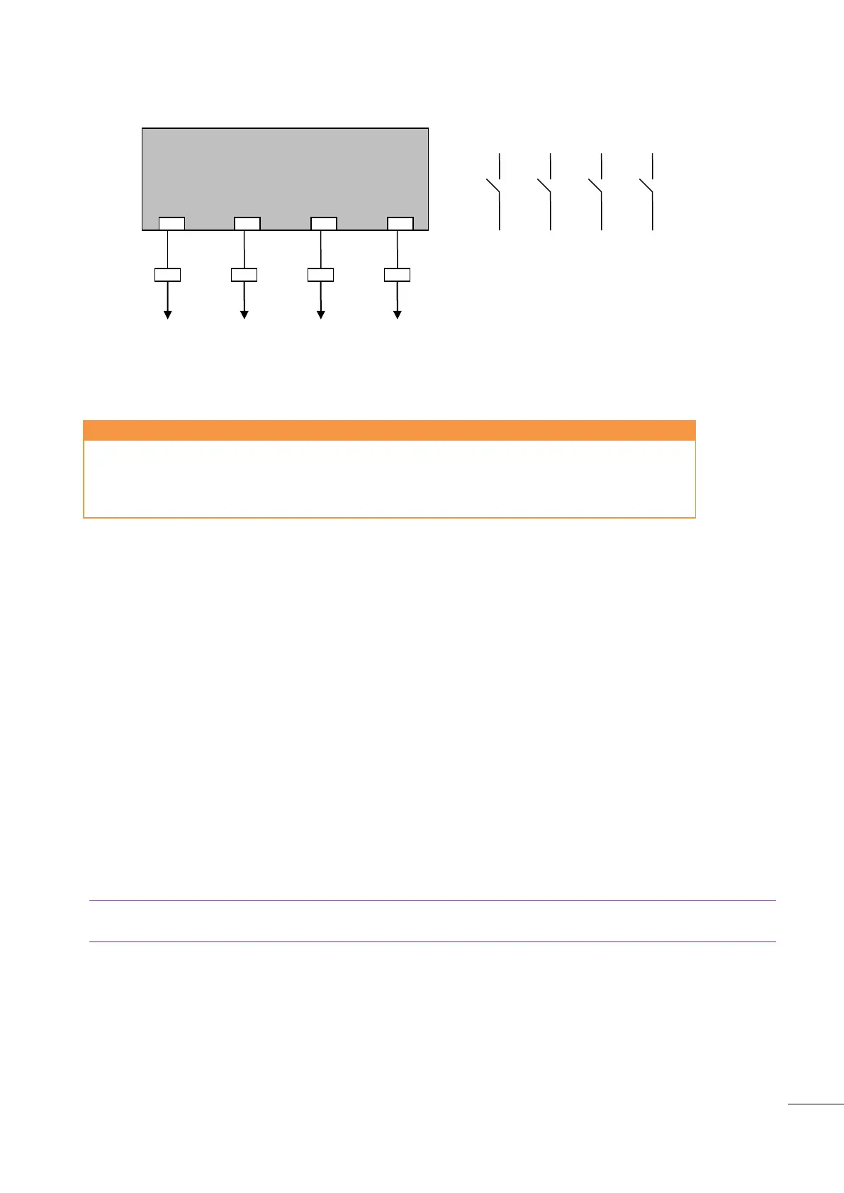
Speed and voltage control with Contacts/Pulses
Figure 44 - Speed and voltage control with Contacts / Pulses
10.2.1
Parameters
Configuration/Outputs/Digital outputs
Configuration/Outputs/Digital outputs
Configuration/Outputs/Digital outputs
Configuration/Outputs/Digital outputs
Table 20 - Parameters speed and voltage control with Contacts / Pulses
10.2.2
Speed Calibration procedure
Here follows the procedure for calibrating the +Hz and –Hz outputs on the GENSYS 2.0, necessary in order
to have good frequency droop compensation and load sharing. (See Figure 45)
Show the following parameter on the information screen: [E2058].
Place the external speed potentiometer in the centre mid position.
Set the following parameters as follows:
-[E1598] on “50” which is about 1 percent load sharing difference (dead band on E2058)
-[E1600] on “2” which is 200 msec. Pulse time
-[E1874] on 2.0 sec. which is pulse pause time for frequency/voltage compensation
-[E1873] on 0.1 sec. which is pulse length for frequency/voltage compensation.
-[E1309] on 0 which is Integral gain (I) phase
-[E1113] on 0 which is Integral gain (I) Frequency.
Note: For best results during synchronization, it's important to set the synchronization GPID to high values
(80 to 20).
1/ Regulation setting (synchronization/load ramp)
If the generator makes too much or not enough correction during an active phase (synchronization, load
sharing,…), the pulse time is bad adjusted:
Decrease [E1600] to reduce the pulse control on the governor
Increase [E1600] to have more correction on the governor.

 Loading...