EasyManuals Logo

Fujitsu PRIMERGY TX1320 M1 Upgrade And Maintenance Manual

Fujitsu PRIMERGY TX1320 M1
340 pages
To Next Page IconTo Next Page
To Previous Page IconTo Previous Page
Page #328 background imageLoading...
Page #328 background image
328 Upgrade and Maintenance Manual
TX1320 M1
Appendix
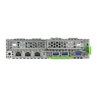
16.3.1.3 Onboard indicators and controls
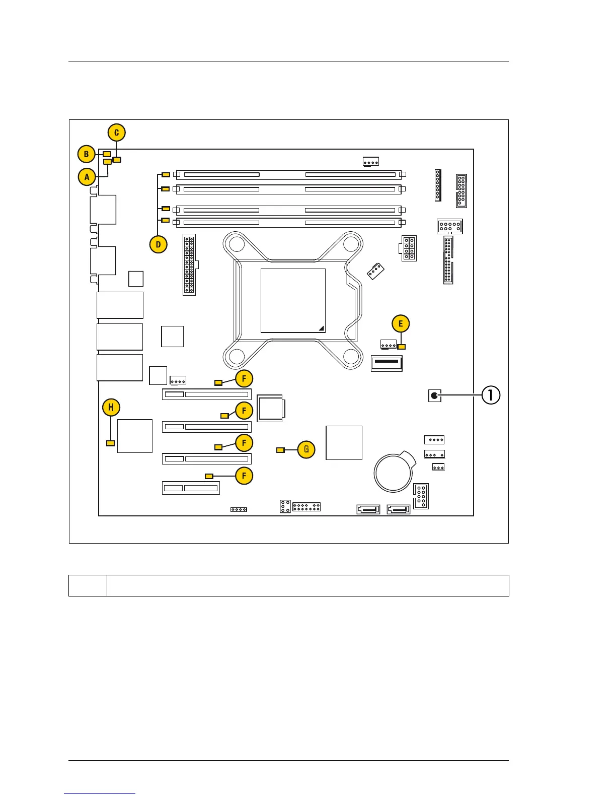
Figure 206: Onboard indicators and Indicate CSS button
Component LEDs
I LEDs A, B and C are visible from the outside on the server rear. All other
LEDs are only visible if the server cover has been opened. In order to
access memory LEDs (D), the system fan module needs to be removed
(see section "Removing the system fan module" on page 153).
1 Indicate CSS button
External connectors
Slot 3 PCIe x8
MLC
SATA1-4
Battery
DIMM1B
Indicate
CSS
CPU
SATA6
SATA
POWER
PWR1
HDD ACTIVITY
Intrusion
TPM
Slot 2 PCIe x4
Management
LAN/
USB 9/10
Shared LAN/
USB 7/8
Standard LAN/
USB 5/6
USB Front
Slot 4 PCIe x8
Slot 1 PCIe x1
Intel
C224
USB1
DAT
USB1AUX
H
iRMC S4
FAN1
SYS
UFM
G
DIMM2B
DIMM1A
DIMM2A
COM1
VGA
SATA5
Intel
i210
Intel
i217
Jumper
PC2009
P30
Frontpanel
Service
LAN
Micro
SD
FAN2SYS
FAN4SYS
FAN3SYS

Table of Contents

Other manuals for Fujitsu PRIMERGY TX1320 M1

Questions and Answers:

Question and Answer IconNeed help?

Do you have a question about the Fujitsu PRIMERGY TX1320 M1 and is the answer not in the manual?

Fujitsu PRIMERGY TX1320 M1 Specifications

General IconGeneral
Processor Sockets1
Memory Slots4
Form FactorTower
ProcessorIntel Celeron
StorageUp to 4 x 3.5" or 2.5" drives
Drive Bays4 x 3.5-inch or 8 x 2.5-inch
RAID SupportRAID 0, 1, 10
Network ControllerDual-port Gigabit Ethernet
Operating System SupportLinux

Related product manuals