D2 Series Servo Drive User Manual Drive Configuration
HIWIN MIKROSYSTEM CORP. 5-53
Table5.6.1
Target radius
Target radius for the position error. After the position error is into
“Target radius” and continues “Debounce time”, “In-Position” is valid.
The default value is 100 times the encoder resolution.
Debounce time
De-bounce time. After the position error is into “Target radius” for
“In-Position” and continues this time, the in-position is valid.
Total time (move time + settling time).
Debounce time setting
The motor positioning may have the overshoot phenomenon, resulting in that the “In-Position” signal
will be instable before the motor reaches the target position. This can be resolved by setting
“Debounce time”. The “In-Position” signal will be sent when the position error enters “Target radius”
and continues to a period of “Debounce time”. The larger “Debounce time” is, the more stable the
“In-Position” signal is, but the larger the time delay is. Through observing on the oscilloscope, the
appropriate “Debounce time” can be set.
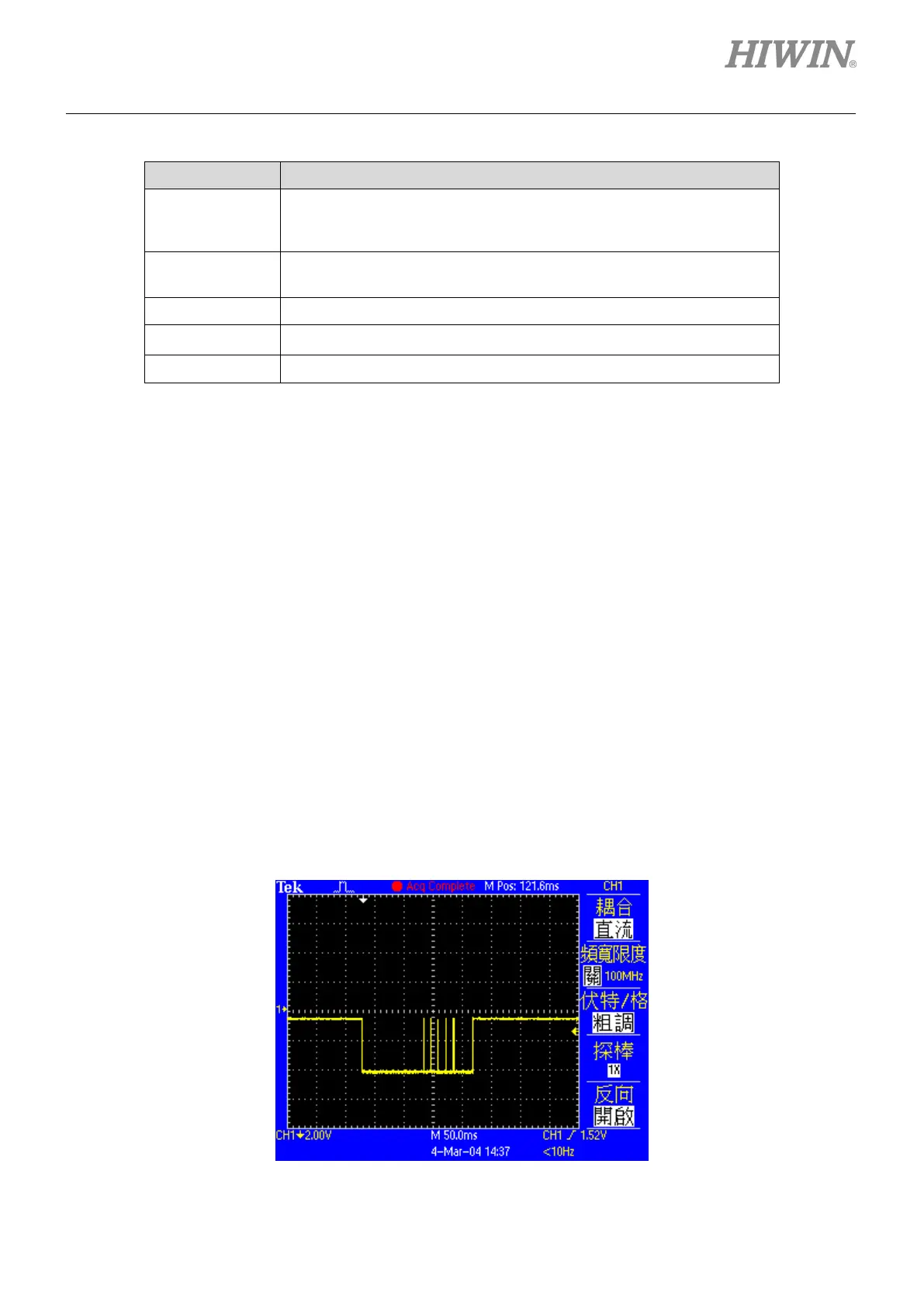
(1) After fixing “Target radius” and setting “Debounce time” to 0 ms, let the motor move a distance
and observe the “In-Position” signal on the oscilloscope, as shown in figure 5.6.2. When
“In-Position” is achieved, the signal is a high level; while when it is not achieved, the signal is a
low level. It can be observed from figure 5.6.2, when the motor moves to near the target
position, there are six protruding pulses (the latter two are closer). Observing the high-level
duration of each protruding pulse, the first one is about 1.5 ms, the second one is about 1.4 ms,
the third one is about 1.4 ms, the fourth one is about 1.3 ms, and the fifth one and the sixth one
are about 1 ms.
Figure5.6.2 In-position signal at “Debounce time” being 0 ms

 Loading...
