D2 Series Servo Drive User Manual Wiring
HIWIN MIKROSYSTEM CORP. 4-15
4.1.6 CN5 Modbus communication/safety function
CN5 connectors of frame A-C models are Modbus communication ports; while the CN5 connector of
frame D model is the input of safety-function device. Check the pin assignment for each model before
use.
(1) Frame A-C
They are Modbus communication ports. Refer to Section 4.1.5.
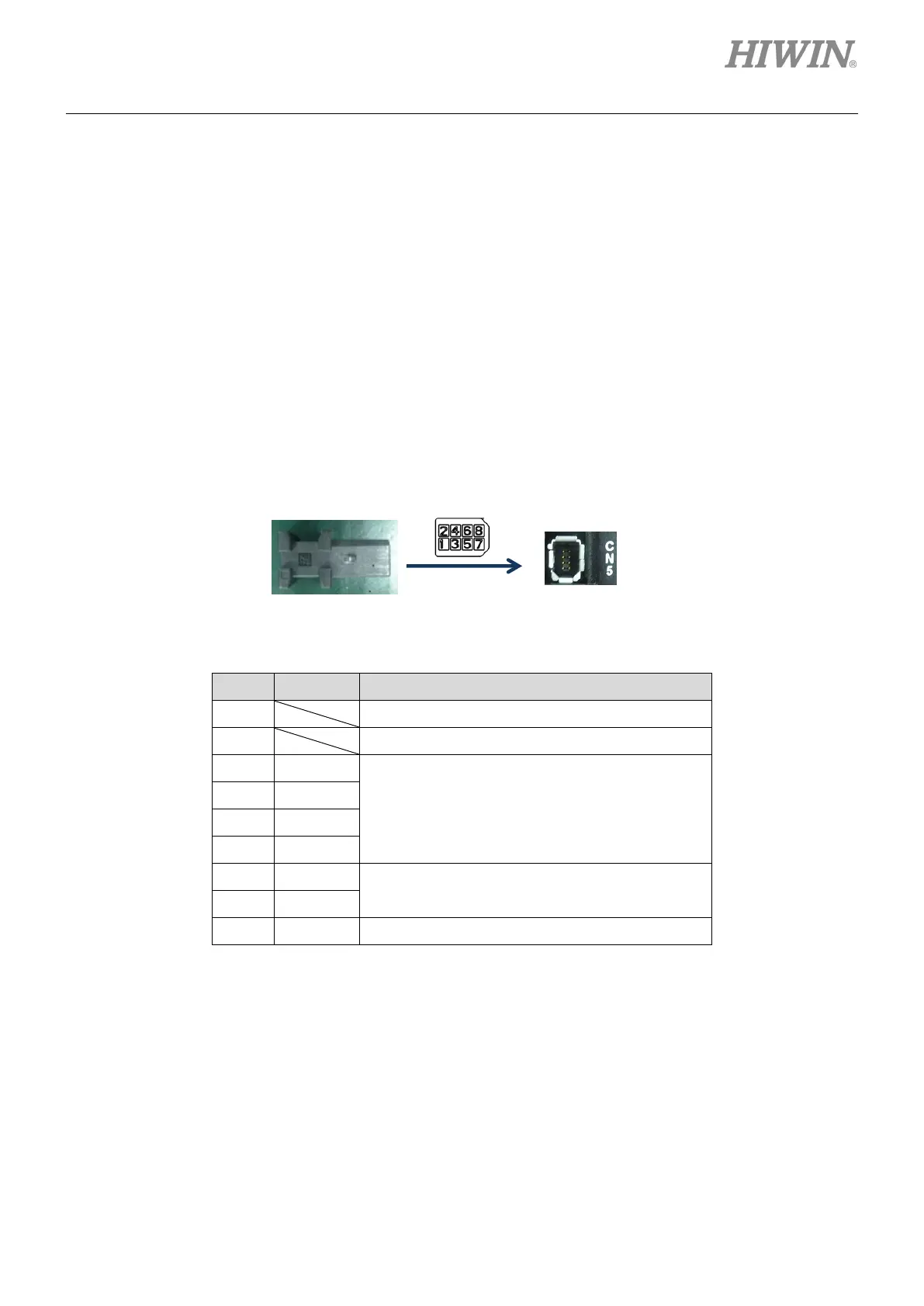
(2) Frame D
If the safety function is not used, connect the supplied safety jumper to CN5. When the safety jumper
is not installed, the drive will not supply current to the motor, and the motor will not work normally.
Connector model: TE Connectivity 1971153-1 (female).
Figure4.1.6.1
Table 4.1.6.1
PIN Function Description
1
Not wiring.
2
Not wiring.
3 SF1-
Two independent circuits for
operation signal of power module, so as to turn
off the motor current.
4 SF1+
5 SF2-
6 SF2+
7 EDM-
Output signal for monitoring the status of safety
function.
8 EDM+
Shell FG
Frame ground reference.
 Loading...

