Operation Principles D2 Series Servo Drive User Manual
3-2 HIWIN MIKROSYSTEM CORP.
3.1 Operation modes
The following operation modes can be used to implement the interface between the standard D2 drive
and the host controller.
(1) Position mode
(2) Velocity mode
(3) Force/torque mode
(4) Stand-alone mode
Each mode is described as follows.
3.1.1 Position mode
The host controller sends pulses to drive. These pulses are equal to position commands. When the drive
receives a pulse, it moves the motor with a corresponding distance. The host controller is responsible for
path planning. The pulse is sent faster and faster at the acceleration, and is sent with a fixed frequency at
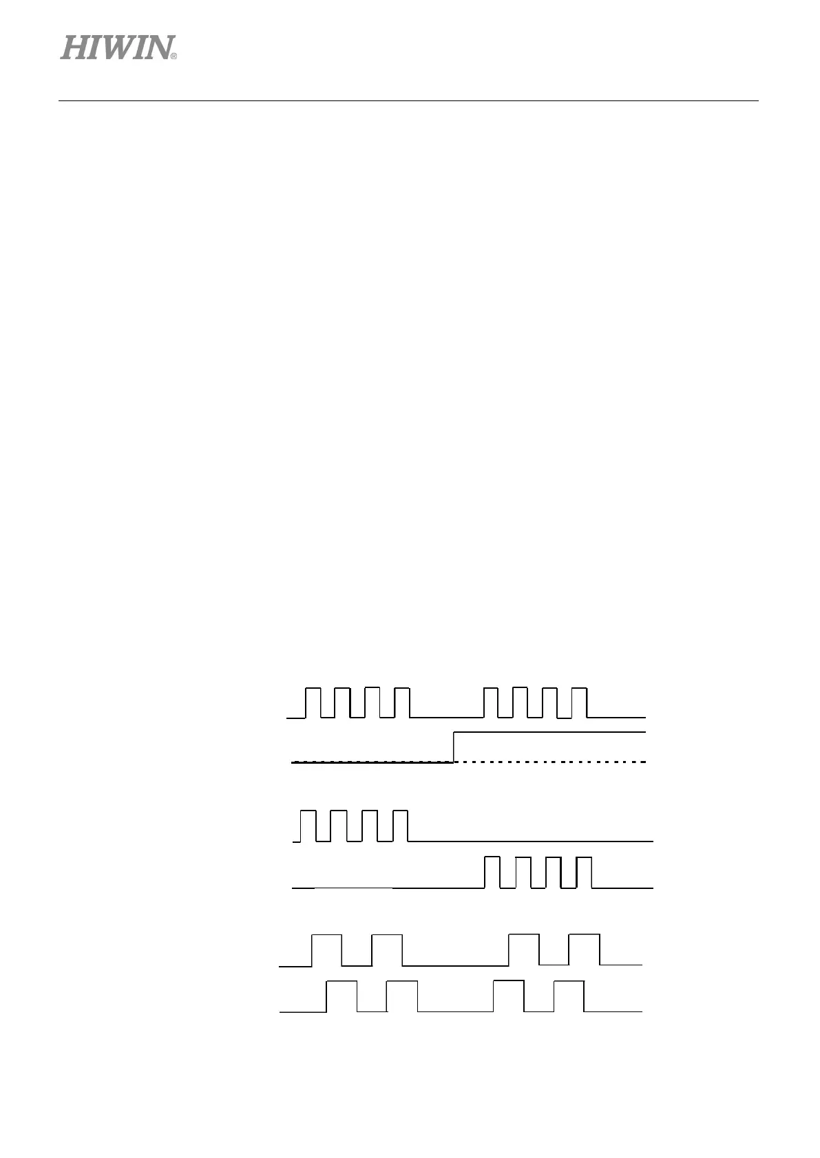
the constant speed. As shown in figure 3.1.1.1, there are three formats of pulse signal: pulse/direction
(pulse/dir), pulse up/pulse down (CW/CCW), and quadrature (AqB). Based on the hardware wiring, the
pulse signal can be classified into the differential and single-end TTL logic signals.
The electronic gear can be set in the position mode. One input pulse is normally set to be equal to one
encoder count. For example, the gear ratio of 2:3 means that 2 input pulses is equal to 3 encoder counts.
Figure3.1.1.1
 Loading...

