Drive Configuration D2 Series Servo Drive User Manual
5-44 HIWIN MIKROSYSTEM CORP.
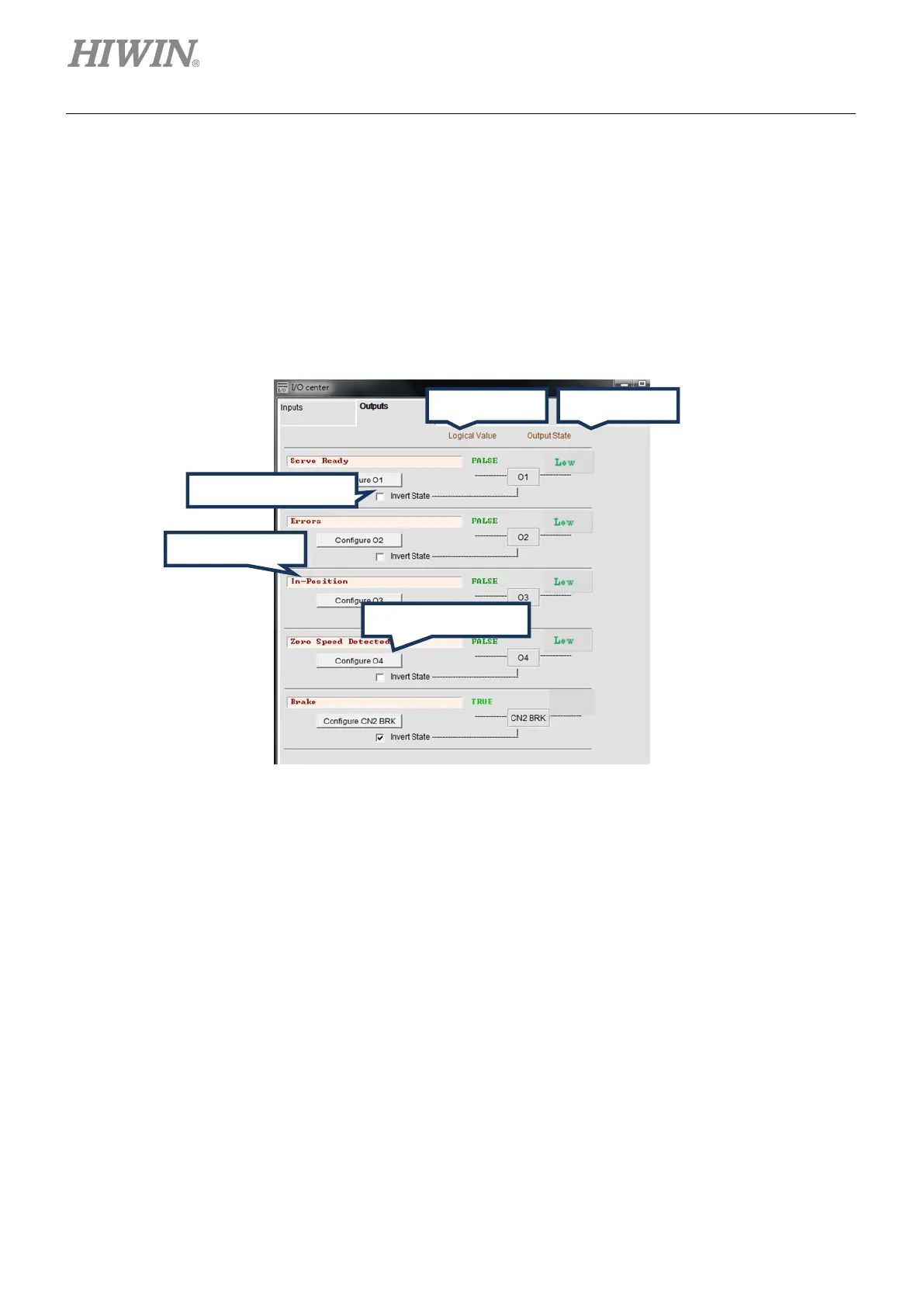
5.5.2 Digital output
D2 model provides 5 sets of programmable digital output. Here, 4 sets (O1 - O4) are general- purpose
outputs located on the CN6 connector. The fifth set (CN2 BRK) is specially designed as the brake output
and can also be used as the general-purpose output. D2T model has more than one general-purpose
output (O5) located on the CN6 connector. In this section, take D2 model as an example to illustrate the
digital output function.
Figure5.5.2.1 Digital output
(1) Logical value
The logical value of each output signal is displayed here. The displayed value is TRUE or FALSE.
(2) Output function
When any item in the function menu on “Configuration” window is checked, the item name is shown
in the status display field. If two or more items are checked, it shows “Customized”. If all error items
are checked, as shown in figure 5.5.2.1, it shows “Errors”. If no item is checked, it shows “PDL usage
(General Purpose)” for the usage of general- purpose output. This means that the output function is
controlled by the PDL program language.
(3) Output state
The current state of drive output pin is displayed here to be low or high (transistor is conducted or not
conducted). This allows to know the state of hardware signal on the drive output to assist in wiring
debugging.

 Loading...
