Wiring D2 Series Servo Drive User Manual
4-30 HIWIN MIKROSYSTEM CORP.
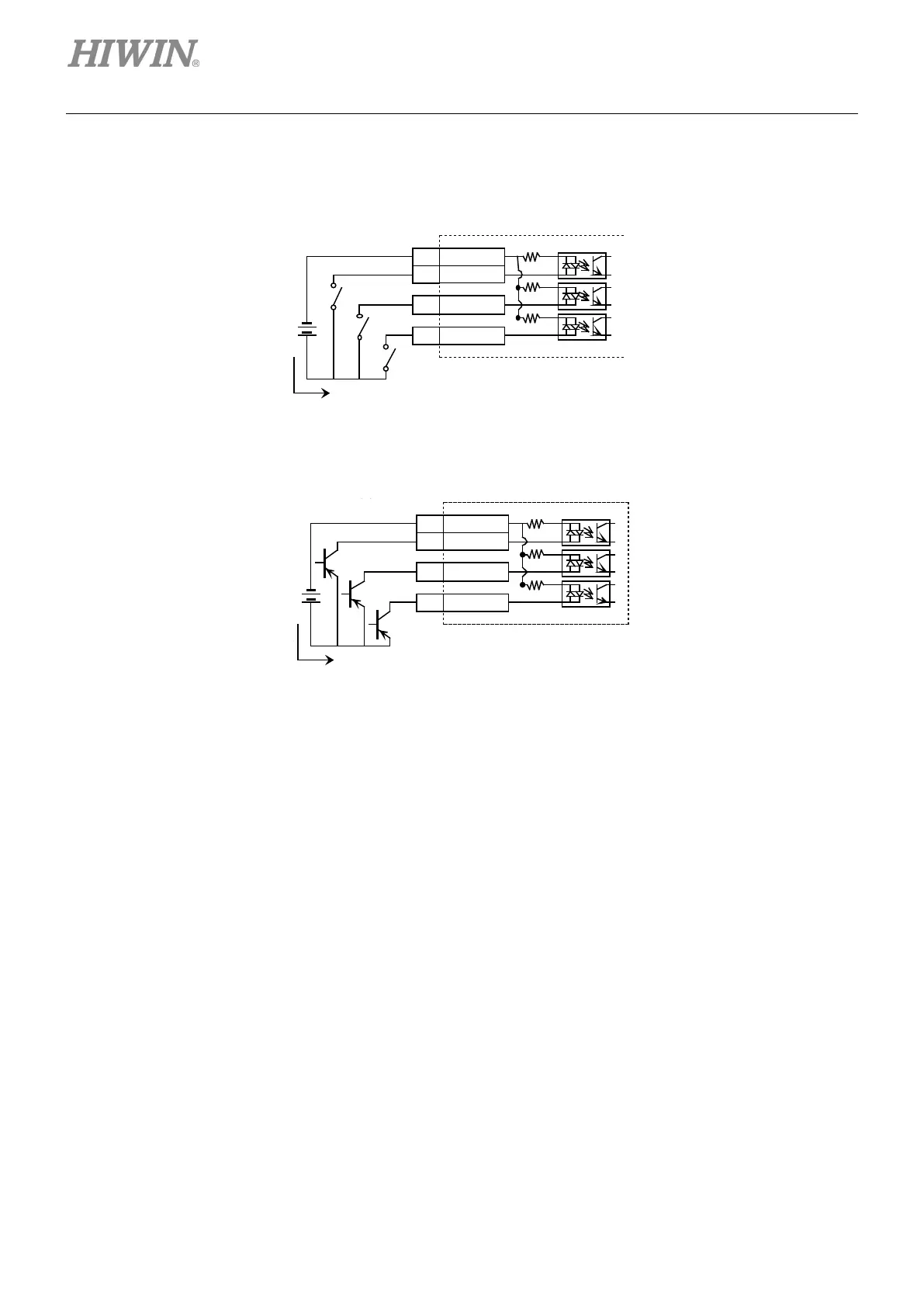
4.5.1.2 Source input wiring examples
Input wiring example via switches or relays
Figure4.5.1.2.1
Input wiring example via transistors
Figure4.5.1.2.2
4.5.2 Digital output wiring
General-purpose outputs of D2-series drive adopt the output interface of optical-coupler Darlington
suitable for the voltage system of less than 24 Vdc. D2 (D2T) model has 4 (5) general-purpose outputs.
Each output has an independent Darlington open-collector circuit. The maximum allowable current is 100
mA. Users can configure the function of each output by using the software.
Note:
When O5 of frame D model is set to brake signal output, it is necessary to connect to a relay to control
the motor brake, since its maximum allowable current is 100 mA.
 Loading...

