Drive Tuning D2 Series Servo Drive User Manual
6-48 HIWIN MIKROSYSTEM CORP.
Note:
(1) “Error map” takes the home position as the start position, and compensates the position in the positive
direction. Therefore, complete the homing procedure before enabling the error map function.
(2) When the host controller needs to receive the feedback pulse outputted from the drive, and also to enable the
error map function, set “Encoder output” in the “Encoder” tab to “Use emulated encoder”.
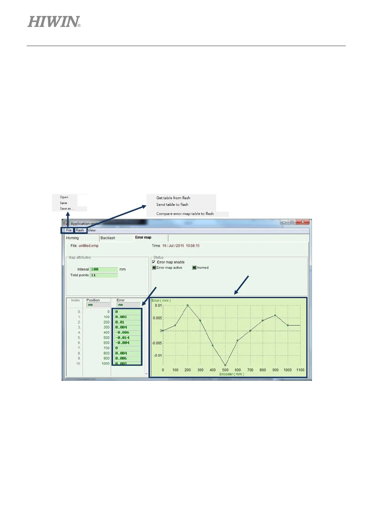
6.9.1 Set error map
The following describes steps of enabling the error map function for D2 drive.
Step 1: Go to the application center and select the “Error Map” tab to open the window of error map
function, as shown in figure 6.9.1.1.
Figure6.9.1.1 Error map window
Step 2: Set the compensation interval (“Interval”) and total compensation points (“Total points”), and
then enter the error compensation value into the “Error” field. If a different custom unit is
needed, click the unit field to set different unit. Taking the example of figure 6.9.1.2, the
compensation range is from 0 to 1,000 mm, the compensation interval is 100 mm, and the total
compensation point is 11 points. The value in the “Error” field is obtained from the error
measurement of laser interferometer. For example, when the target position is 100 mm, the
laser measurement returns to 100.002 mm.
Error compensation value
for each position
 Loading...

