D2 Series Servo Drive User Manual Drive Tuning
HIWIN MIKROSYSTEM CORP. 6-49
Figure6.9.1.2 Parameter setting of error map
Note:
(1) When the error compensation value is entered into the table, the entered value is rounded to an integer
multiple of encoder resolution. For example, if the encoder resolution is 2 um and the entered compensation
value is 1 um, the program will forcibly convert it to 2 um. If the input is 0.5 um, it will be converted to 0 um.
(2) Because the displayed accuracy is only to the third decimal, select the appropriate unit for “Position” and
“Error”.
Step 3: Check the option of “Error map enable” ( ).
Step 4: Choose the “Send table to flash” option of “Flash” in the function menu. If there are other
parameters modified except error map parameters, and not yet saved in Flash, the following
window will be displayed. If there is no parameter needed to save except error map parameters,
go to Step 6.
Figure6.9.1.3
reminder to
inform that the
modified
compensation
value has not
been saved to
the drive’s
Flash.
Current parameters except error map parameters are different from those
in the drive’s Flash. If click the “Continue” button to save error map
parameters to Flash, servo parameters will be lost due to the forced
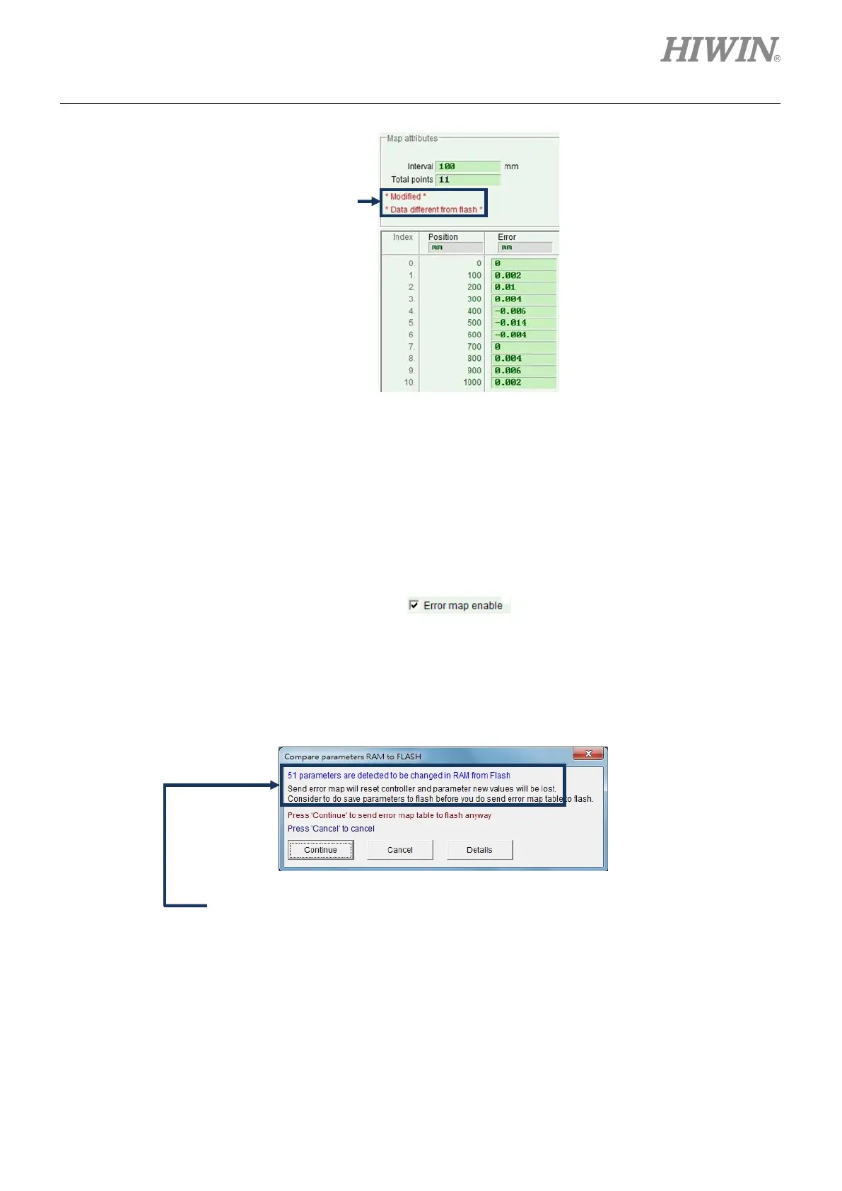 Loading...

