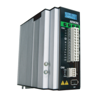
D2 Series Servo Drive User Manual Specifications
HIWIN MIKROSYSTEM CORP. 2-3
2.1.3 Model number
Table 2.1.3.1
Code 1 2 3 - 4 5 6 7 - 8 - 9 10
Example D 2 - 0 4 2 3 - S - B 0
1, 2: Product D2 = D2 series servo drive
3: Type
T = 17-bit encoder only
blank = 13-bit encoder only
4, 5: Rated output
01 = 100W
04 = 400W
10 = 1.0KW
20 = 2.0KW
6, 7: Voltage range
23 = 1/3-phase 220Vac
32 = 3-phase 220Vac
8: Interface
S = Standard
E = EtherCAT (CoE)
F = EtherCAT (mega-ulink)
K = Standard with extension I/O module
T = Standard with Modbus
9: Frame size
A = A frame (100W)
B = B frame (400W)
C = C frame (1.0KW)
D = D frame (2.0KW)
10: Encoder type
0 = 13-bit less-wire incremental encoder
4 = 17-bit serial incremental encoder (HIWIN 17)
5 = Dual loop (full closed loop) and 17-bit serial absolute encoder
Note:
(1) The standard model supports the pulse and +/- 10 V input interfaces.
(2) The EtherCAT (CoE) and EtherCAT (mega-ulink) models do not have the extension I/O module and Modbus
module.
(3) The frame D model requires the voltage range of 3-phase 220 Vac.
(4) D2 model does not support the extension I/O module and the rated output of 2.0 KW.
(5) D2T frame A, B, and C models do not have the Modbus module.
(6) For the dual-loop model, the rotary encoder should be the 17-bit serial absolute encoder and the linear
encoder should be the digital AqB encoder.
(7) The EtherCAT (CoE) model does not support the dual-loop control.

 Loading...