Drive Tuning D2 Series Servo Drive User Manual
6-40 HIWIN MIKROSYSTEM CORP.
(1) U (s): System input. It is the drive command.
(2) Y (s): System output. It is the position feedback of encoder.
(3) Plant: PL(s) is the relationship between the drive command and the feedback position. The plant
contains the mechanical platform, motor, and feedback system.
(4) Controller: P(s) is the position loop controller, V(s) is the velocity loop controller, and C(s) is the
current loop controller.
(5) Open loop: The transfer function of open loop system is “G(s) =P(s)*V(s)*C(s)*PL(s)”, meaning to
ignore all feedback signals.
(6) Close loop: The transfer function of close loop system is
T(s) = P(s)*V(s)*C(s)*PL(s)/((d/dt*P(s)*V(s)*C(s)*PL)+P(s)*V(s)*C(s)*PL(s)).
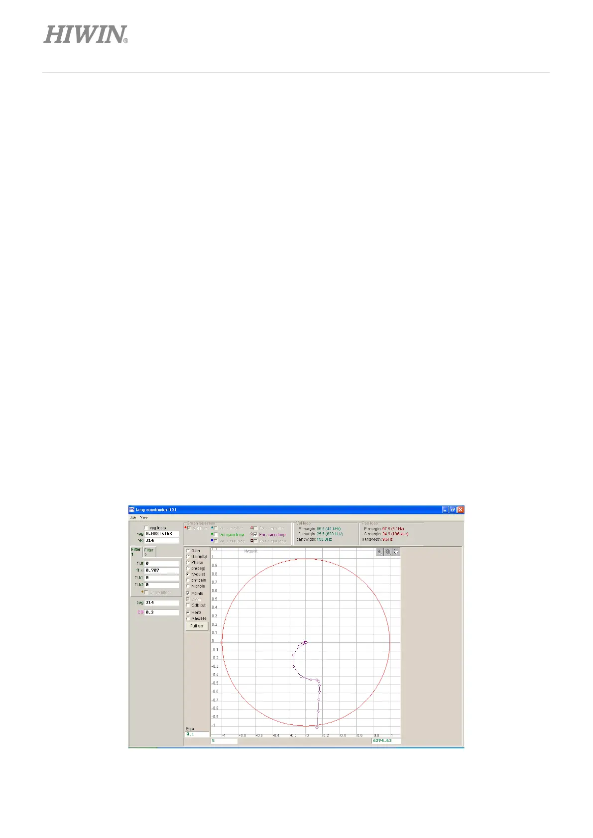
6.7.2.2 Nyquist
The “Nyquist” option of “Loop constructor” can analyze and simulate frequency responses of “Vel open
loop” (velocity open loop) and “Pos open loop” (position open loop) of control system. Using the check
method can select to analyze and simulate the Nyquist diagram of “Velocity open loop” or “Position open
loop”. It can also select two loops to analyze and simulate at the same time. The Nyquist plot of “Pos open
loop” is shown in figure 6.7.2.2.1. Clicking the curve on the Nyquist plot displays the value of frequency
response for the analysis of control system.
(1) Vel open loop: The frequency response of the velocity open loop of control system.
(2) Pos open loop: The frequency response of the position open loop of control system.
Figure6.7.2.2.1 Nyquist plot of position open loop

 Loading...
