D2 Series Servo Drive User Manual Wiring
HIWIN MIKROSYSTEM CORP. 4-43
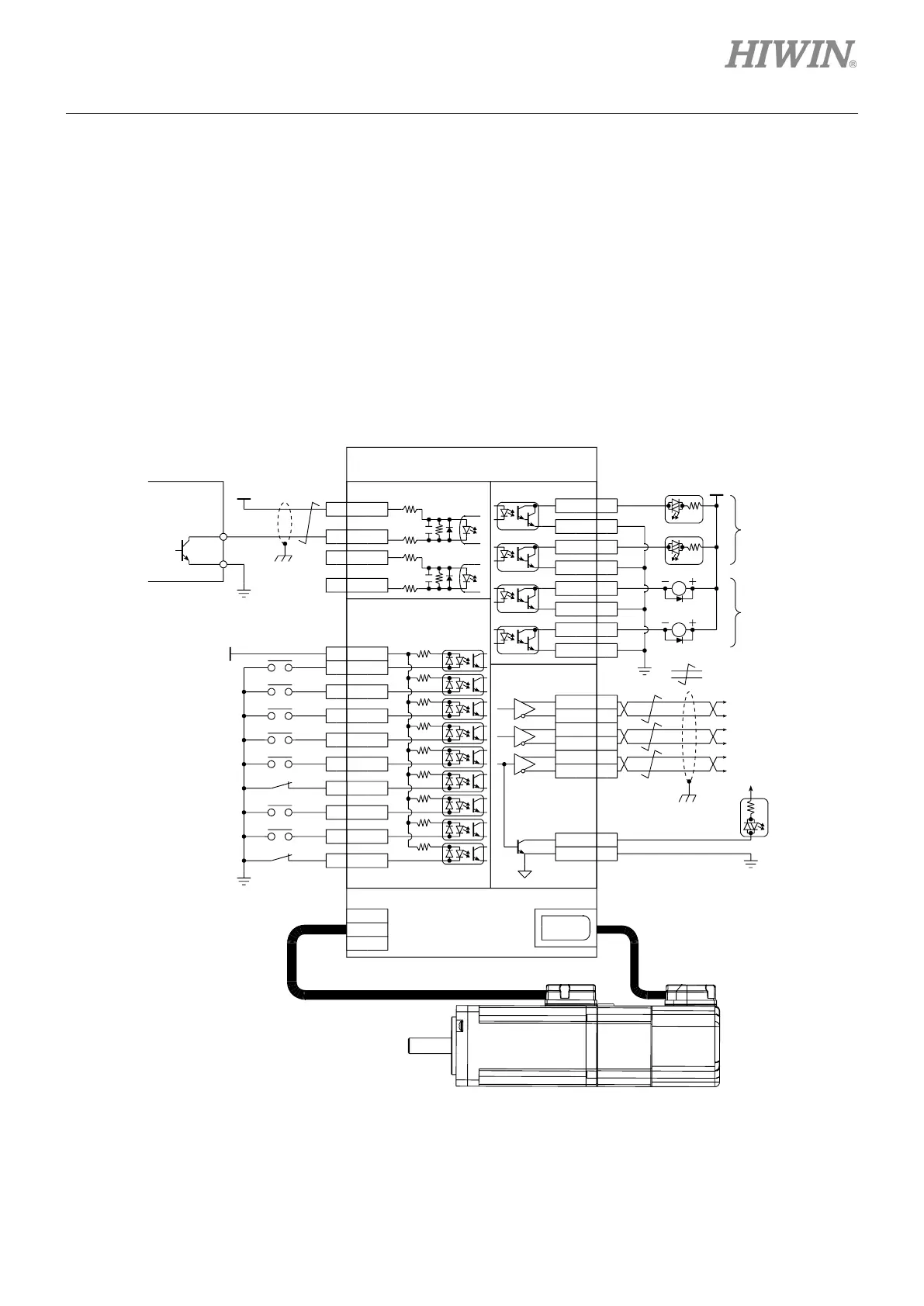
4.6.3 System wiring diagram for PWM command
In addition to analog voltage command, D2-series drives can also accept the PWM command in the
velocity and force/torque modes. The PWM command is classified into single-wire (PWM 50%) and
two-wire (PWM 100%) types. Refer to Sections 3.1.2 and 3.1.3 for more information.
4.6.3.1 NPN interface with PWM 50%
Wiring example for the host controller having the NPN interface with PWM 50%:
Figure4.6.3.1.1
W
V
U
CN1 CN7
CN6
4
CWL-
220
2K
220
2K
6
CCWL-
COM7
I133
I230
I329
I427
I5
28
I626
I732
I831
I99
4.7K
CN6
21
A
22/A
48B
49
/B
23Z
24/Z
19CZ
CN6
Encoder output
25SG
Signal output
Signal input
Velocity / Torque mode
ZSP
SVN
GNS
26
LL
MOD
CE
RL
24V
0V
0V
12~24VDC
A-phase
output
Z output (open collector)
0V
B-phase
output
Z-phase
output
PWM 50% command
mega-fabs
D2 Series Drive
1
CWL
2 CCWL
2K
D2-ENE13A
2K
0V
PWM
( :Twisted pair)
Ic=0.6A(Max.)
Vce=40V(Max.)
CN6
O1+ 35
O1- 34
O2+
37
O2- 36
O3+ 39
O3-
38
O4+ 11
O4- 10
24V
R
RDY
ALM
INP
Photo-
Coupler
wiring
Relay
wiring
R
General-purpose output;
its function can be
assigned by the user.
General-purpose
input; its function
can be assigned by
the user.

 Loading...
