Wiring D2 Series Servo Drive User Manual
4-16 HIWIN MIKROSYSTEM CORP.
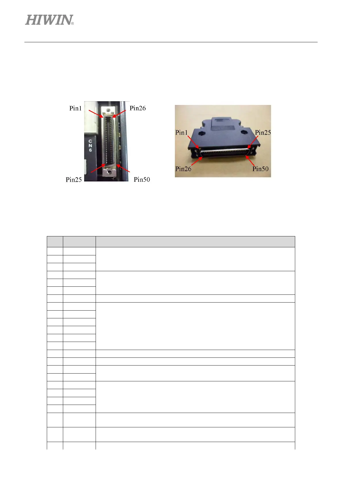
4.1.7 CN6 control signal
For the pulse command and PWM command, the high-level input voltage should be greater than 2 V, and
the low-level input voltage should be less than 0.8 V.
Figure4.1.7.1
CN6 pin assignment
Table4.1.7.1
Pin Signal Function
Low-speed (500 Kpps) pulse command
Channel 1: Pulse, CW, A-phase
Low-speed (500 Kpps) pulse command
Channel 2: Dir, CCW, B-phase
Ground reference for digital signal
Feedback pulse output (buffered encoder or emulated encoder)
RS422
Z-phase output (open collector)
Analog command input for the velocity/torque (+/- 10 V)
N/A
43 AO1
Analog voltage output (+/- 10V) for monitoring motor torque (only for D2T
model)
42 AO2
Analog voltage output (+/- 10V) for monitoring motor speed (only for D2T
model)
High-speed (4 Mpps) pulse command

 Loading...
