D2 Series Servo Drive User Manual Operation Principles
HIWIN MIKROSYSTEM CORP. 3-5
Figure3.2.2
3.3 Encoder signal output
The input signal of encoder is used to perform the servo control by the servo drive. When the drive works
with the host controller, the host controller also has the requirement of receiving position signal. Normally,
the drive will transmit the position or angle signal received from the encoder to the host controller. D2
drive provides the following two modes of encoder output.
Buffered encoder output
When this mode is selected, the drive sends the received encoder signal to the host controller
directly. Besides, if the invert of encoder signal is required, check the option of invert function. At this
time, the drive inverts the received encoder signal and sends it out.
Emulated encoder output
When this mode is selected, the drive multiplies the received encoder position by a scale and sends
it out to the host controller. For some cases, if the host controller cannot receive the encoder signal
with a too high frequency, the scale can be set to lower the frequency of encoder output. In addition,
if the multiplier factor of analog encoder is set too high, the scale can also be set to lower the
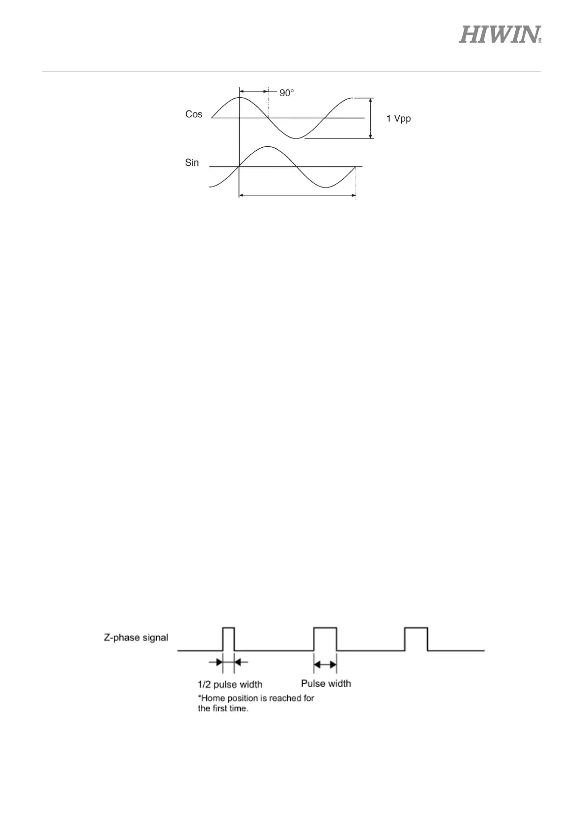
resolution of encoder output. When motor reaches home position for the first time, the width of output
Z-phase signal is half of its original width.
Figure3.3.1

 Loading...
