Drive Tuning D2 Series Servo Drive User Manual
6-52 HIWIN MIKROSYSTEM CORP.
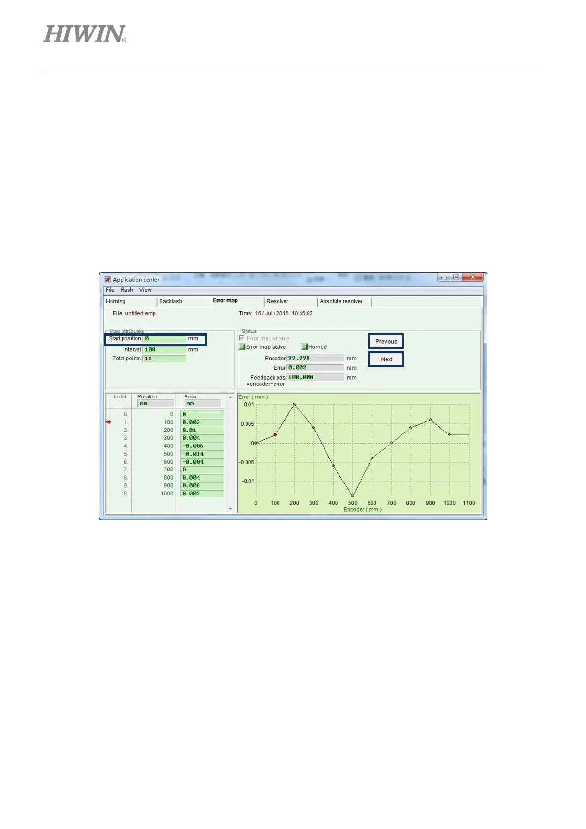
6.9.4 Change start position
If it is needed to change the start position of error map, select the “Advanced” option of “View” in the
function menu to appear the window of figure 6.9.4.1. Enter the required start position of compensation in
the “Start position” field. In addition, pressing the “Next” button on the right side of window, the motor will
move the distance of one “Interval” in the forward; while pressing the “Previous” button, the motor will
move the distance of one “Interval” in the reversal. The “Error” value in the “Status” area is updated to the
error compensation value corresponding to the current position. The red dot on the graph of “Error Map” is
the “Encoder” value, and the “Feedback position” value is equal to the “Encoder” value plus the “Error”
value.
Figure6.9.4.1
Note:
To compensate the errors in negative direction, input the stop point in Start position field and set the interval in
Interval field. For instance, input -1000 in Start position field, 100 in Interval field and 11 in Total points field. Then
the compensation positions will be -1000, -900, -800, …, -100, 0, starting from index 0.
(1) “Home offset” = 0 and “Start position” = 0
For the setting of both “Home offset” and “ Start position” being zero, the effective range of error map
takes the index as the boundary. The area from the index towards positive direction is the mapping
effective area; while the area from the index towards negative direction is the area without mapping.

 Loading...
